
Novel boiler front feeding device of straw biomass CFB boiler

A feeding device and biomass technology, which is applied in the direction of combustion type, fuel burned in a molten state, lighting and heating equipment, etc., can solve the problems that affect the safe and stable operation of the boiler, low stacking density of biomass fuel, and poor fluidity

Inactive Publication Date: 2012-07-04
宿迁市凯迪绿色能源开发有限公司
View PDF7 Cites 17 Cited by
  • Summary
  • Abstract
  • Description
  • Claims
  • Application Information

AI Technical Summary

Problems solved by technology

[0004] Therefore, there are many kinds of biomass fuels, with great differences in physical properties. Due to their light and soft texture and poor fluidity, they are easy to be entangled, bridged, and arched during transportation, especially for soft straw materials, and the phenomenon of material entanglement is serious.
In addition, due to the low bulk density and low calorific value of biomass fuel, the volume to be transported is relatively large
However, when dealing with straw materials, the conventional screw feeding device often has problems such as smearing, blocked rotation, material jamming and material blocking, which leads to unstable operation of biomass utilization process equipment and affects the safe and stable operation of the boiler.
[0005] At the same time, due to the special national conditions of our country, the collection, storage, transportation, and pretreatment modes are quite different from those of foreign countries. The domestic biomass fuel has a strong particularity, and it is difficult to ensure the ideal length during the cutting process. The arch phenomenon is very common, resulting in poor material feeding and feeding, affecting the combustion conditions of biomass direct-fired boilers

Method used


Image

  • Novel boiler front feeding device of straw biomass CFB boiler
  • Novel boiler front feeding device of straw biomass CFB boiler
  • Novel boiler front feeding device of straw biomass CFB boiler

Examples


Embodiment Construction

[0010] The present invention will be described in detail below in conjunction with the accompanying drawings.

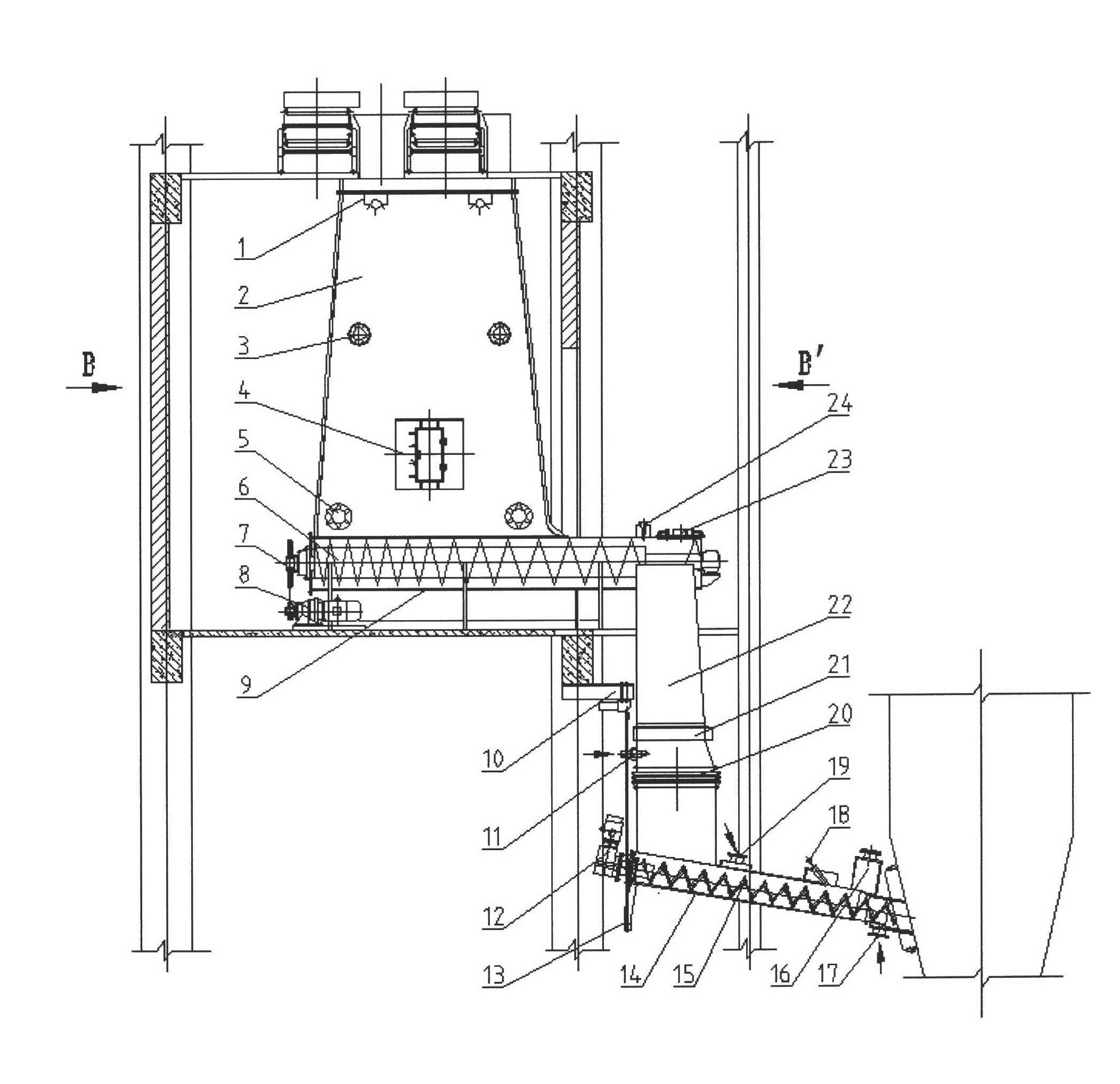
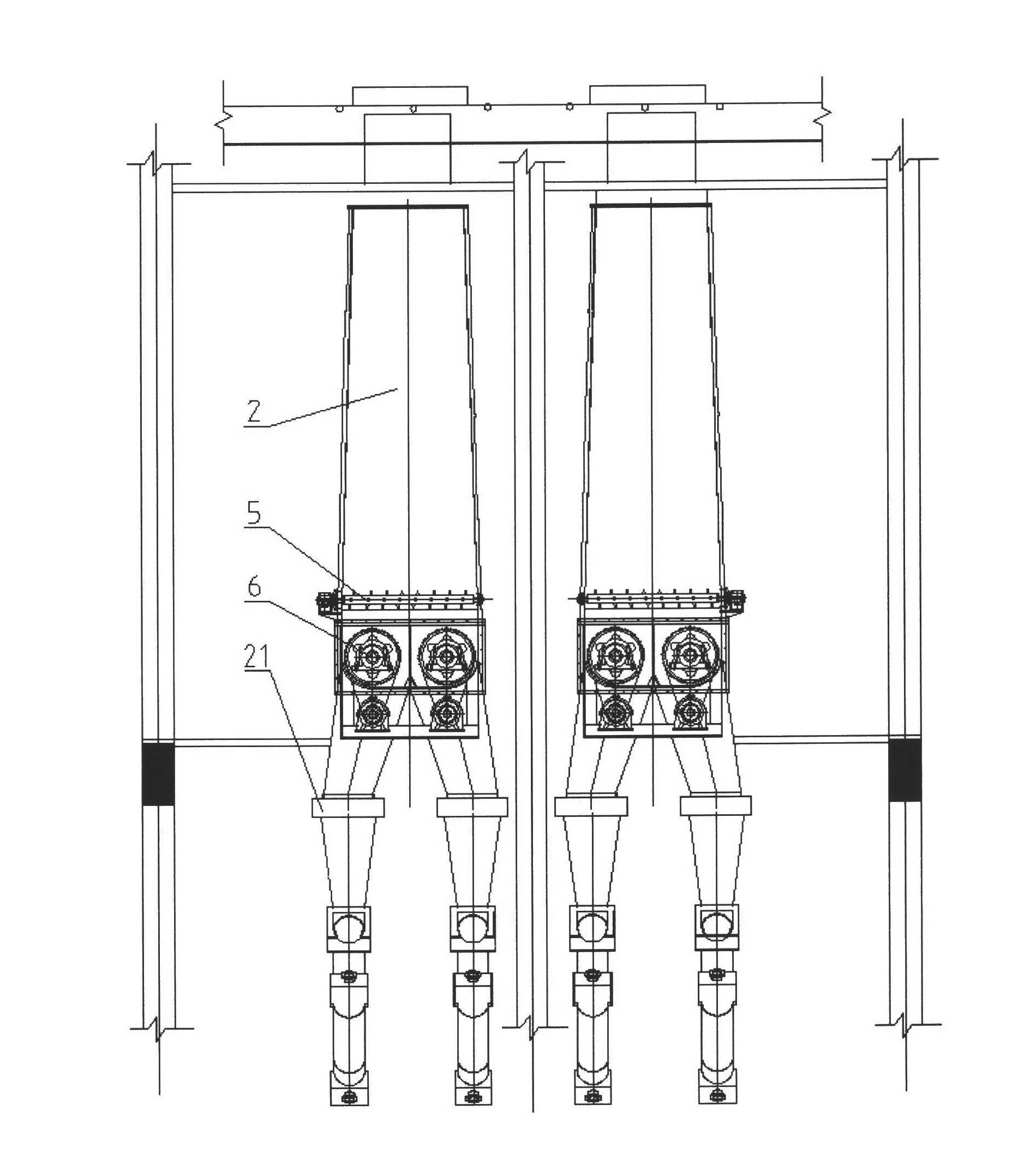
[0011] like figure 1 and figure 2 As shown, a new type of straw biomass CFB boiler furnace feed device, including the furnace feed bin assembly, a primary batching screw assembly, a drop pipe assembly, a secondary feeding screw assembly and a safety control assembly, the furnace front The silo assembly includes two silos 2, an infrared camera 1 is installed on the top of each silo 2, an explosion-proof release valve 3 is installed in the middle of both sides of the silo 2, and a manhole door 4 is arranged in the outer middle of the silo 2. The lower part of each silo 2 is provided with two activators 5, and the activators 5 are arranged near the front and rear walls of the silo 2 along the direction of the unloading screw axis, and are arranged at 500 mm above the lower part of the silo 2; The screw assembly includes two sets of double-row large-diameter shafted s...


PUM

PropertyMeasurementUnit
Lengthaaaaaaaaaa
Diameteraaaaaaaaaa
Lengthaaaaaaaaaa

Abstract

The invention discloses a novel boiler front feeding device of a straw biomass CFB (circulating fluidized bed) boiler, which includes a boiler front feed bin assembly, a first-stage blending spiral assembly, a blanking pipe assembly, a second-stage feeding spiral assembly and a safety control assembly, wherein the boiler front feed bin assembly includes two feed bins; an infrared camera is mounted at the top end in each feed bin; explosion-proof relieve valves are installed at the middle parts of the two sides of each feed bin; a manhole door is arranged at the middle part on the outer side of each feed bin; and two activators are arranged at the lower part of each feed bin. The novel boiler front feeding device fully combining the structural characteristics of the screw feeder, adopts the brand-new model that the feeding process sectional functions are decomposed and the safety fire-prevention measures are reasonably linked, and can satisfy the high load of the boiler and has excellent use effect for all sorts of biomass fuels as proven by practice.

Description

technical field [0001] The invention relates to a feeding device in front of a boiler furnace, in particular to a new straw biomass CFB (CFB Circulating Fluidized Bed) technology, which has greater fuel applicability and pollutant discharge than the pulverized coal combustion technology. Advantages of combustion technology) Boiler front feeding device. Background technique [0002] Biomass power generation technology is a new technology that converts biomass energy into electric energy, mainly using crop straw and forestry waste as fuel for power generation. [0003] The fuel of straw power plants is generally divided into gray straw, yellow straw and shells. Gray straw includes: cotton stalks, branches, mulberry sticks and other hard straws; yellow straw mainly includes: corn straw, wheat straw, rice straw and other soft straws; Shells are mainly: rice husks, peanut shells, etc. [0004] Therefore, there are many kinds of biomass fuels, with great differences in physical ...

Claims


Application Information

Patent Timeline
IPC IPC(8): F23C10/22
Inventor 胡锋杜文春王品纪袁光生苏永亚连东京
Owner 宿迁市凯迪绿色能源开发有限公司
Learn More