
System and method utilizing flue duct waste gas of hot air furnace to bake and preheat charging of blast furnace

A technology of flue exhaust gas and hot blast stove, which is applied to blast furnaces, preheating costs, and details of blast furnaces. It can solve problems such as single function, affecting normal production of blast furnaces, and high manufacturing costs, so as to enhance the screening effect and avoid gas explosion. Dangerous, easy-to-make effects

Active Publication Date: 2012-07-04
SHOUGANG CORPORATION
View PDF8 Cites 17 Cited by
  • Summary
  • Abstract
  • Description
  • Claims
  • Application Information

AI Technical Summary

Problems solved by technology

[0004] In the prior art, the blast furnace is equipped with a silo, the silo is provided with a material inlet and a material outlet, and the material outlet is provided with a supporting plate device, and the silo is only used for storing and batching materials, and has a single function and It is indispensable, and the manufacturing cost is very expensive. There is nothing to do with the blast furnace charge with rain or snow. It can only let the charge enter the furnace with rain, snow and powder, which affects the normal production of the blast furnace.

Method used


Image

  • System and method utilizing flue duct waste gas of hot air furnace to bake and preheat charging of blast furnace
  • System and method utilizing flue duct waste gas of hot air furnace to bake and preheat charging of blast furnace
  • System and method utilizing flue duct waste gas of hot air furnace to bake and preheat charging of blast furnace

Examples


Embodiment Construction

[0034] Specific embodiments of the present invention will be described in detail below in conjunction with the accompanying drawings.

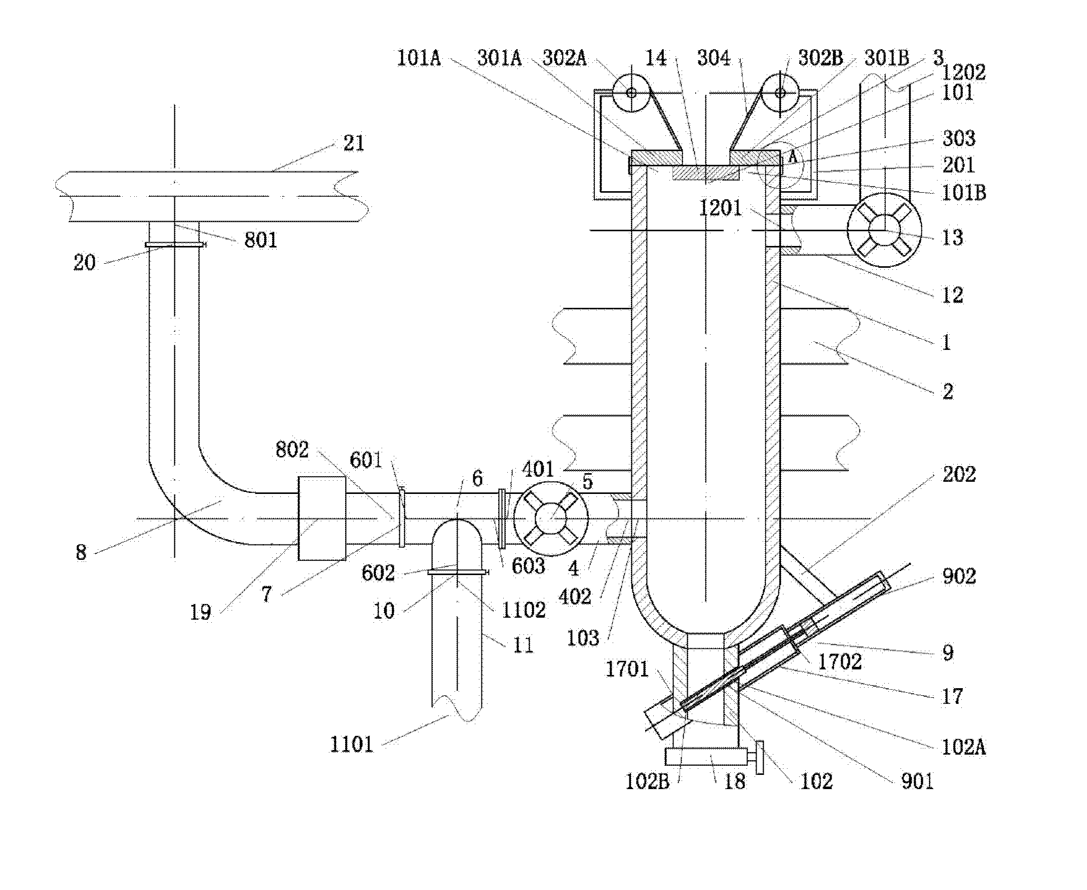
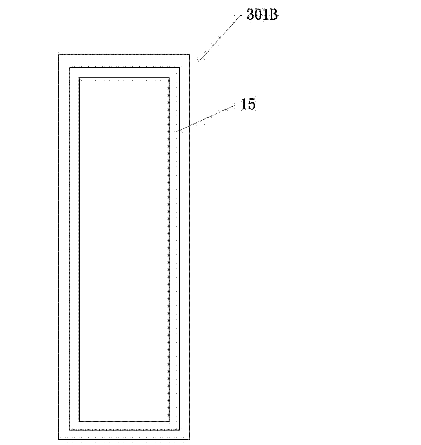
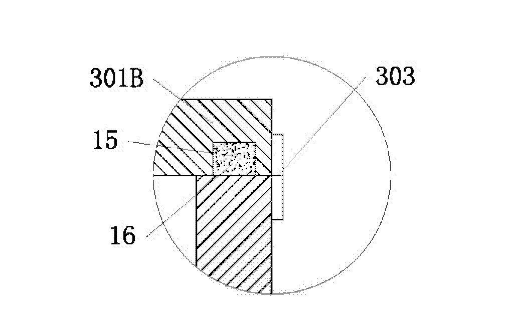
[0035] Such as figure 1As shown, the present invention utilizes the flue gas of the hot blast stove to bake and preheat the system of the blast furnace charge, which includes a silo 1, which is a vertical columnar shell (the present embodiment takes a square quadrangular prism shell as an example), and the silo 1 Supported in the air by the support 2, the bottom is a conical arc surface or a spherical conical arc surface ( figure 1 The bottom shown in is a spherical arc), such a bottom structure is easy to discharge; the feed bin 1 is provided with a feed port 101 and a discharge port 102, and the feed port 101 is arranged on the top of the feed bin 1, figure 1 The feed inlet 101 shown in is equivalent to the top of the silo 1, and is basically square, with its side length forming a ring-shaped end face. The middle part of the two inner walls...


PUM


Abstract

The invention discloses a system and a method utilizing flue duct waste gas of a hot air furnace to bake and preheat charging of a blast furnace. The system includes a storage bin, wherein a feed opening of the storage bin is provided with a sealing cover device; an air inlet of the storage bin is sealed and communicated with an outlet end of an air inlet channel; an induced draft fan is arranged on the air inlet channel; an exhaust opening of the storage bin is sealed and communicated with an inlet end of an air exhaust channel; and an exhaust fan is arranged on the air exhaust channel. The method includes the steps as follows: A), loading the storage bin with the charging, and closing the sealing cover at the feed opening and an air supplementing control valve; B), opening an induced draft control valve, starting the induced draft fan and the exhaust fan, introducing flue duct waste gas in the hot air furnace into the storage bin through an induced draft pipeline, and directly baking the charging; C), closing the induced draft control valve and opening the air supplementing control valve, enabling air to enter the storage bin through an air supplementing pipeline, and further quickly discharging residual waste gas in the storage bin through the air exhaust channel; and D), stopping the induced draft fan and the exhaust fan, and discharging the charging in the storage bin. The system and the method provided by the invention are mainly used for baking and preheating the charging in the blast furnace through the flue duct waste gas of the hot air furnace.

Description

technical field [0001] The invention belongs to the technical field of blast furnace ironmaking, and in particular relates to a system and a method for baking and preheating blast furnace charge by utilizing flue gas of a hot blast stove. Background technique [0002] The temperature of the exhaust gas produced during the combustion of the blast furnace hot blast stove is 200°C to 330°C, and its main components include CO 2 (23~28%), N 2 (70-76%), O 2 (1 to 2%) and trace amounts of CO. Most of the flue gas of blast furnace hot blast stove is directly discharged to the atmosphere, and its heat source is wasted. In recent years, with the pressure of blast furnace costs and the enhancement of energy awareness, the use of flue gas has gradually begun to be emphasized. For example, the Chinese invention patent application publication CN85108099A (application number 85108099) discloses a method and device for utilizing waste heat of blast furnace hot blast stove flue gas , The...

Claims


Application Information

Patent Timeline
IPC IPC(8): F27D17/00F27D13/00C21B7/00C21B5/00
Inventor 张勇魏丽艳苏展孙健
Owner SHOUGANG CORPORATION
Learn More