Magnetic force microscopy probe with low magnetic moment and high coercive force and manufacturing method thereof

A magnetic force microscope, high coercivity technology, applied in scanning probe technology, scanning probe microscopy, measuring devices, etc., can solve the problems of low and medium coercivity, low magnetic moment and high coercivity

Active Publication Date: 2012-07-04
CENT IRON & STEEL RES INST
View PDF2 Cites 7 Cited by
  • Summary
  • Abstract
  • Description
  • Claims
  • Application Information

AI Technical Summary

Problems solved by technology

[0004] The magnetic films of the magnetic probes in the prior art are CoCr, CoNi, Co, Ni alloys, etc., which are basically low or medium coerci

Method used


Image

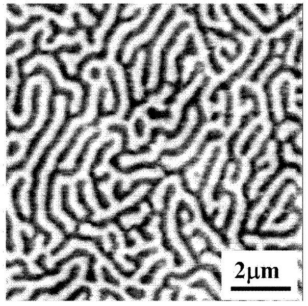
  • Magnetic force microscopy probe with low magnetic moment and high coercive force and manufacturing method thereof
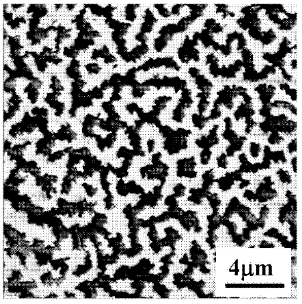
  • Magnetic force microscopy probe with low magnetic moment and high coercive force and manufacturing method thereof
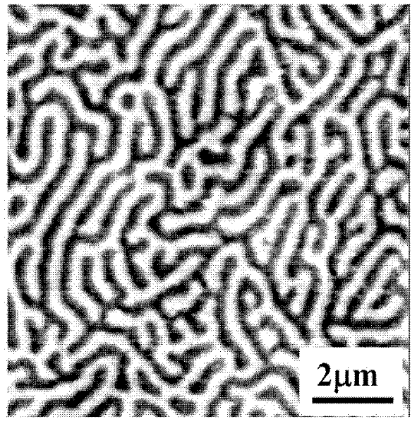
  • Magnetic force microscopy probe with low magnetic moment and high coercive force and manufacturing method thereof

Examples


Embodiment 1

[0028] The method for manufacturing the magnetic force microscope probe with low magnetic moment and high coercive force according to embodiment 1 comprises the following steps:

[0029] 1. Clean the Si probe with acetone or alcohol;

[0030] 2. Fix the above-mentioned Si probe after cleaning in the sample chamber of the magnetron sputtering apparatus, and evacuate the sample chamber. At this time, the vacuum of the sample chamber can be 1×10 -5 Below Pa, after that, high-purity inert gas is introduced to maintain the pressure of the sample chamber at 0.5 Pa;

[0031] 3. CoPt magnetic alloy (Pt atoms account for 45% of the total number of atoms in the CoPt alloy) is sputtered onto the surface of the above-mentioned Si probe by magnetron sputtering, the sputtering time is 15 minutes, and the sputtering power is 30 watts. Thereby obtaining a magnetic coating with a thickness of 30nm;

[0032] 4. Heat the obtained Si probe with magnetic coating to 500°C under high vacuum condit...

Embodiment 2

[0037]The method for manufacturing the magnetic force microscope probe with low magnetic moment and high coercive force according to embodiment 2 comprises the following steps:

[0038] 1. Clean the Si probe with acetone or alcohol;

[0039] 2. Fix the above-mentioned Si probe after cleaning in the sample chamber of the magnetron sputtering apparatus, and evacuate the sample chamber. At this time, the vacuum of the sample chamber can be 1×10 -5 Below Pa, after that, high-purity inert gas is introduced to maintain the pressure of the sample chamber at 0.3 Pa;

[0040] 3. CoPt magnetic alloy (Pt atoms account for 50% of the total number of atoms in the CoPt alloy) is sputtered onto the surface of the above-mentioned Si probe by magnetron sputtering, the sputtering time is 30 minutes, and the sputtering power is 5 watts. Thereby obtaining a magnetic coating with a thickness of 10nm;

[0041] 4. Heat the obtained Si probe with a magnetic coating to 650°C under high vacuum condit...


PUM

PropertyMeasurementUnit
Thicknessaaaaaaaaaa
Coercivityaaaaaaaaaa
Saturation magnetizationaaaaaaaaaa

Abstract

The invention relates to a magnetic force microscopy probe with a low magnetic moment and a high coercive force and a manufacturing method thereof; the manufacturing method comprises the following steps of: cleaning a Si probe; fixing the cleaned Si probe in a sample chamber of a magnetic control sputtering device, vacuumizing the sample chamber, and then feeding a high-purity inert gas to lead the gas pressure in the sample chamber to be maintained at 0.1-0.5 pascal; sputtering a CoPt magnetic alloy on the surface of the Si probe in a magnetic control sputtering manner, thereby obtaining the Si probe with a magnetic coating; and heating the obtained Si probe with the magnetic coating in a vacuum condition to be 500 DEG C-750 DEG C, and carrying thermal treatment for 15-180 minutes so that the magnetic alloy is converted into the L10-CoPt alloy, thereby obtaining the magnetic force microscopy probe with the low magnetic moment and the high coercive force.

Description

technical field [0001] The invention relates to a magnetic force microscope probe and a manufacturing method thereof, in particular to a low magnetic moment and high coercivity magnetic force microscope probe and a manufacturing method thereof. Background technique [0002] Magnetic force microscopy (MFM), as a micro-magnetic structure detection device, has been widely used in the characterization of the magnetic domain structure of magnetic materials. The main working principle of the magnetic force microscope is to use the interaction between the magnetic probe and the stray magnetic field on the sample surface to scan above the sample at a certain height (the distance between the probe and the sample) to detect the distribution of the magnetic force gradient on the sample surface to obtain the sample The micro-magnetic structural characteristics of magnetic materials can be studied to study the magnetic properties of magnetic materials. [0003] The MFM detection device ...

Claims


Application Information

Patent Timeline
IPC IPC(8): G01Q60/50G01Q60/56
Inventor 方以坤朱明刚刘涛郭朝晖李卫
Owner CENT IRON & STEEL RES INST
Why Eureka
Try Eureka