Method for measuring time constant of rotor of asynchronous machine

A rotor time constant and asynchronous motor technology, which is applied in motor generator testing, AC motor control, electrical components, etc., can solve problems such as complex calculations and large measurement errors, and achieve the effects of accurate values, simple algorithms, and simple measurement methods

Active Publication Date: 2012-07-04
杭州兆鼎科技实业有限公司
View PDF7 Cites 13 Cited by
  • Summary
  • Abstract
  • Description
  • Claims
  • Application Information

AI Technical Summary

Problems solved by technology

[0006] In order to overcome the shortcomings of the existing off-line measurement method of the time constant of the asynchronous motor, such as complex calculation and large measurement error, the present invention provides a method for measuring the rotor time constant of the asynchronous motor that simplifies the calculation and effectively reduces the measurement error.

Method used


Image

  • Method for measuring time constant of rotor of asynchronous machine
  • Method for measuring time constant of rotor of asynchronous machine
  • Method for measuring time constant of rotor of asynchronous machine

Examples


Embodiment Construction

[0020] Further illustrate the present invention below in conjunction with accompanying drawing.

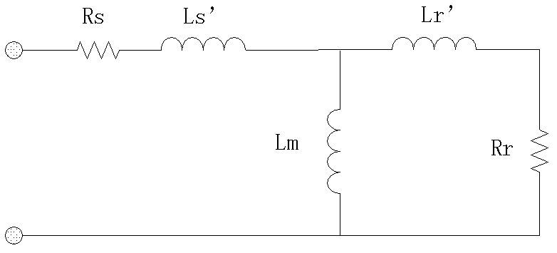
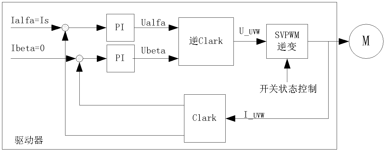
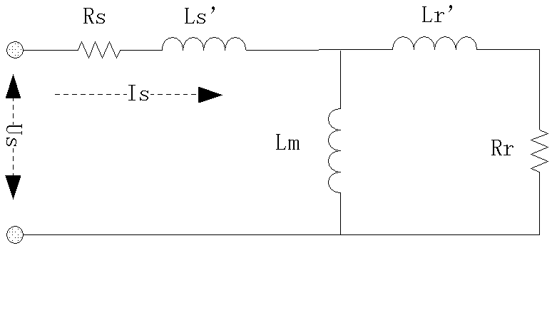
[0021] refer to Figure 1 to Figure 6 , a method for measuring the rotor time constant of an asynchronous motor. The inverter or servo drive connected to the asynchronous motor contains an inverter bridge. When the inverter bridge is in the inverter state, when the stator current and voltage are zero , given the stator current I s , the working time is t m , when the magnetizing current reaches the maximum value I m0 , record I m0 ; excitation t m After that, the inverter bridge is immediately closed, and after a period of time, the stator current is zero; after the stator is cut off, the inverter bridge is set to a three-phase short-circuit state, and the stator current I s Gradually rising from zero, I s reaches the maximum I sz , record I sz , waiting for the motor current decay excitation to be zero, the measurement method includes the following steps:

[0022] a) Giv...


PUM


Abstract

The invention discloses a method for measuring a time constant of a rotor of an asynchronous machine. An inverter or a servo driver connected with the asynchronous machine comprises an inverter bridge; when the inverter bridge is in an inversion state, stator current is given to be Is0 and the working time is given to be tm under the condition that the stator current and voltage are zero, and the magnetizing current reaches the maximum Im0 which is recorded; after excitation is carried out for tm, the inverter bridge is immediately in a closed state, and the stator current is zero after a period of time; after a stator is cut off, the inverter bridge is set to be in a three-phase short circuit state, the stator current Is is gradually raised from zero, when the Is reaches the maximum Isz, the Isz is recorded, and the current of the asynchronous machine is waited to be subjected to excitation attenuation to reach zero; and the Isz is compared with IszO, and when the compared difference is in a set error range, the time constant of the rotor of the asynchronous machine is working time tm1. By the method, calculation can be simplified and measurement errors can be effectively reduced.

Description

technical field [0001] The invention relates to a parameter method for measuring an asynchronous motor, and more specifically, relates to a method for measuring a time constant of an asynchronous motor. Background technique [0002] Due to high speed accuracy and fast torque response, vector control technology for asynchronous motors is widely used in many industrial fields. The rotor time constant Tr of the asynchronous motor is an important parameter of the asynchronous motor, especially when using vector control, it directly affects the accuracy of the magnetic field orientation. [0003] figure 1 The equivalent model of the asynchronous motor shown, where Rs is the stator resistance, Ls' is the stator leakage inductance, Rr is the rotor resistance, Lr' is the rotor leakage inductance, Lm is the mutual inductance, s is the slip, the definition of the rotor time constant is : [0004] T r = L ...

Claims


Application Information

Patent Timeline
Patent Type & Authority Applications(China)
IPC IPC(8): G01R31/34H02P27/06
Inventor 罗欣吴立沈安文饶文培
Owner 杭州兆鼎科技实业有限公司
Why Eureka
Try Eureka