
Trapping and detecting multiplexed scanning optical-tweezers system

An optical tweezers and beam technology, applied in the field of scanning optical tweezers system, can solve the problems of application, complex system, difficult to achieve effective and high-precision detection, etc., and achieve the effect of reducing cost and simplifying optical tweezers device

Inactive Publication Date: 2012-07-04
UNIV OF SCI & TECH OF CHINA
View PDF4 Cites 18 Cited by
  • Summary
  • Abstract
  • Description
  • Claims
  • Application Information

AI Technical Summary

Problems solved by technology

When the particle size is too large, its image exceeds the size of the detection target surface, making it difficult to achieve effective and high-precision detection
[0006] In the design of the photoelectric detection of scanning optical tweezers, the forward detection device makes the system complex, but it can detect the position of the captured particles in the scanning optical trap; the back detection device is simple, but the detection method for particle imaging is difficult in the scanning optical tweezers. application

Method used


Image

  • Trapping and detecting multiplexed scanning optical-tweezers system
  • Trapping and detecting multiplexed scanning optical-tweezers system
  • Trapping and detecting multiplexed scanning optical-tweezers system

Examples


Embodiment Construction

[0024] The present invention will be described in detail below in conjunction with the accompanying drawings and specific embodiments, but the scope of protection of the present invention is not limited to the following examples, but should include all content in the claims.

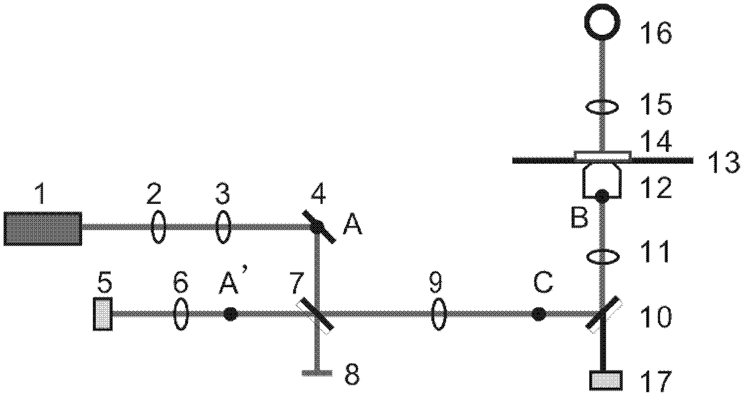
[0025] The scanning optical tweezers capture and detection multiplexing optical path design of the present invention is based on a commercialized infinity microscope system, the capture beam and the detection beam are the same laser beam, see the schematic diagram figure 1 . In the optical tweezers system of the present invention, the capture optical path design parameters need to meet the following conditions: (1) the beam scanning position is conjugate to the rear focal plane of the objective lens; The beam expansion ratio depends on the design requirements of the beam scanning range; (3) The spot size of the captured beam entering the objective lens is consistent with the optical aperture size of the ...


PUM


Abstract

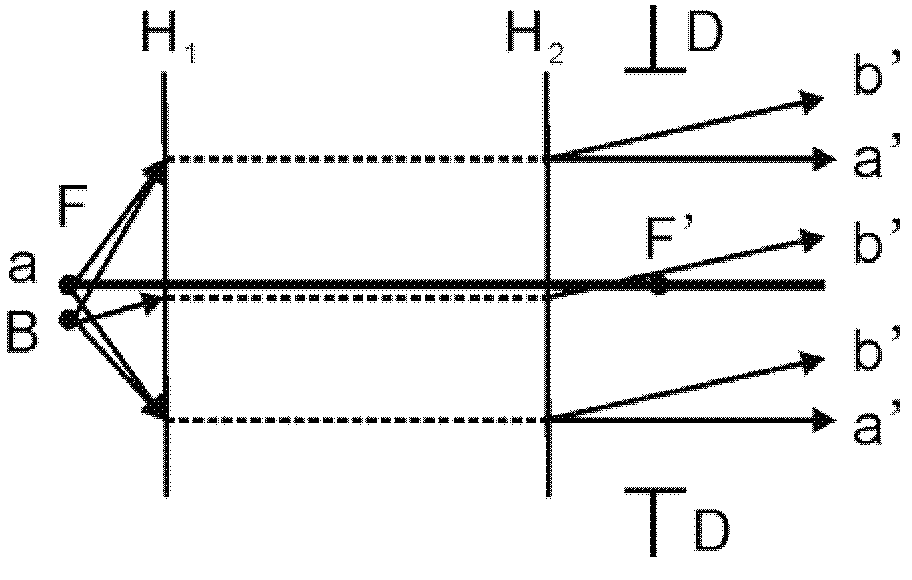
The invention provides a trapping and detecting multiplexed scanning optical-tweezers system. The trapping and detecting multiplexed scanning optical-tweezers system works by the following steps of: scanning a conjugate surface of a back focal plane of an objective lens to trap light beams to form a pair of scanning optical tweezers; collecting trapped small ball scattering light spots on the back focal plane of the objective lens, and projecting the light spots of the back focal plane of the objective lens onto a four-quadrant detector in a conjugate imaging manner; multiplexing an optical path by a trapping optical path and a detecting optical path through a half-reflecting and half-transparent plane mirror; changing symmetry of light spots when particles deviate the center of a light trap so as to realize high-precision detection on the displacement of the particles; and realizing detection of the light beam on the displacement of the scanning optical tweezers because the conjugate image central position of the light spots of the particles on the back focal plane of the objective lens is still placed on a target surface of a detector when the optical tweezers scan. The trapping and detecting multiplexed scanning optical-tweezers system provided by the invention simplifies a system design of the traditional scanning optical tweezers and also keeps the detection of the optical tweezers at different scanning positions so as to realize requirements on high-precision detection.

Description

technical field [0001] The invention belongs to the technical field of optical micro-manipulation systems, in particular to a scanning optical tweezers system for capture and detection multiplexing. Background technique [0002] Optical tweezers with scanning function are widely used in the study of biological macromolecules, such as the study of protein folding structure, DNA stretching properties and ligand-receptor interactions. In these applications, the optical trap of optical tweezers is used to capture the handle ball modified with biomacromolecules, move to the target such as biomacromolecule or cell that needs to be contacted, and then perform a specific scanning motion on the handle ball through the optical trap, so that When biomacromolecules are subjected to specific stress, the mechanical properties of the structural changes of biomacromolecules can be studied. The optical tweezers with scanning function need to be able to quickly track the position of the part...

Claims


Application Information

Patent Timeline
Patent Type & Authority Applications(China)
IPC IPC(8): G02B21/36G02B21/32G21K1/00G01N21/01
Inventor 周金华王自强钟敏成周丹丹李银妹
Owner UNIV OF SCI & TECH OF CHINA
Learn More