
Photoetching machine exposure method

An exposure method and lithography machine technology, applied in the field of lithography machine exposure, can solve the problems of equipment production capacity reduction, unsuitability for large-scale production, etc., and achieve the effect of large process window and uniform contrast of exposure graphics

Active Publication Date: 2012-07-04
CSMC TECH FAB2 CO LTD
View PDF7 Cites 0 Cited by
  • Summary
  • Abstract
  • Description
  • Claims
  • Application Information

AI Technical Summary

Problems solved by technology

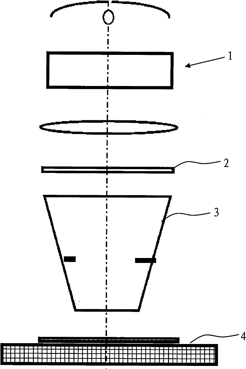
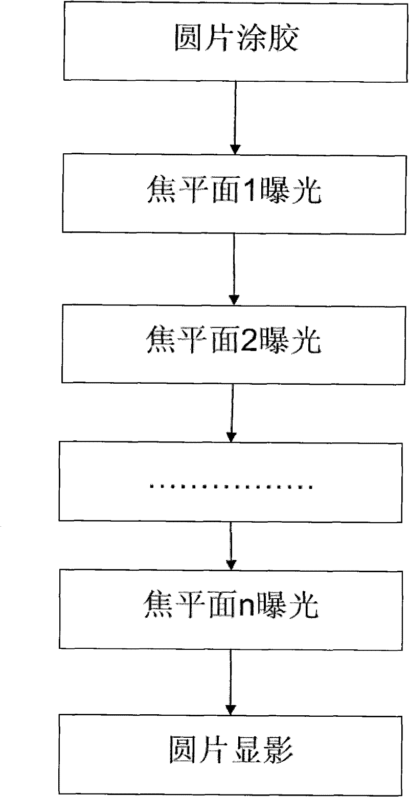
[0005] When the stepper lithography machine is imaging, the pattern of the lithography plate is imaged through the entire lens area at one time. Therefore, repeated exposure with multiple focal lengths can only be done by changing the focal length multiple times and repeating exposure multiple times. The sacrifice of production capacity is inevitable. of
[0006] In addition, under normal circumstances, the lens plane of the scanning stepper is parallel to the plane of the wafer or the plane of the photolithography plate, and the same method as the stepper can be used to move the upper and lower distances of the wafer stage Changing the focal length to complete multi-focal length repeated exposure, but this is also at the expense of productivity
[0007] The above-mentioned existing multi-focal length repeated exposure method increases the original conventional exposure method from one time to multiple times. Although the process window of lithography is increased, the production capacity of the equipment is reduced, which is not suitable for mass production.

Method used


Image

  • Photoetching machine exposure method
  • Photoetching machine exposure method
  • Photoetching machine exposure method

Examples


Embodiment Construction

[0021] The best mode for carrying out the present invention will be described below with reference to the drawings.

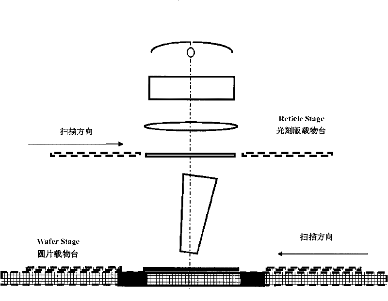
[0022] like image 3 As shown, the exposure method of the scanning stepper lithography machine disclosed in the present invention is applicable to the hole process and the bright field / dark field strip / space process in the photolithography process. During exposure, the lens is first adjusted and tilted at a certain angle along the scanning direction of the photolithography stage and the wafer stage, so that the focal length of the light projected onto the wafer through the slit-shaped lens is gradually changed; secondly, Exposure is performed by scanning the photoresist plate loading platform and the wafer loading platform. By adopting such a method, the effect of repeated exposure with multiple focal lengths can be obtained in one exposure, and a larger process window can be obtained. Of course, the wafer stage and the photolithography plate stage must alway...


PUM


Abstract

The invention provides a photoetching machine exposure method which is used for scanning a stepping photoetching machine. The photoetching machine exposure method comprises the following steps of: 1, inclining a slit-shaped lens for a certain angle along a scanning direction of a photoetching mask objective table and a wafer objective table so that the focal length of light projected to a wafer from the slit-shaped lens is gradually changed; and 2, scanning the photoetching mask objective table and the wafer objective table to perform exposure. Compared with the prior art, the photoetching machine exposure method has the beneficial effects that one-time exposure is equivalent to the conventional multi-focal-length repeated exposure, so the method is convenient and quick; furthermore, the focal length range is changed continuously and linearly; and in a focal depth range, an exposed picture has more uniform contrast and a larger technical window can be obtained.

Description

technical field [0001] The invention relates to an exposure method for a photolithography machine, in particular to an exposure method for a scanning and stepping photolithography machine. Background technique [0002] In the modern semiconductor lithography process, in order to improve the lithography process window, multi-focal length repeated exposure is a commonly used technology. With the reduction of the line width of the semiconductor process, Resolution Enhancement Technology (RET, Resolution Enhancement Technology) is also widely used in the advanced process. One of the techniques is to take multiple exposures at different focal length planes to increase the focal depth range (DOF, depth of focus) of the exposure, and at the same time improve the entire lithography process window (DOF-EL, Depth of Focus and Exposure Latitude ). In the multiple focal length exposure method, the final image contrast pair is homogenized in the entire focal length range, and the image...

Claims


Application Information

Patent Timeline
Patent Type & Authority Applications(China)
IPC IPC(8): G03F7/20
Inventor 黄玮
Owner CSMC TECH FAB2 CO LTD
Learn More