
System and method capable of realizing energy stability of injected laser

A laser energy and energy technology, applied in the field of laser applications, can solve problems such as laser energy instability, and achieve the effect of ensuring stability and achieving stable gain.

Inactive Publication Date: 2012-07-04
BEIJING GK LASER TECH
View PDF5 Cites 3 Cited by
  • Summary
  • Abstract
  • Description
  • Claims
  • Application Information

AI Technical Summary

Problems solved by technology

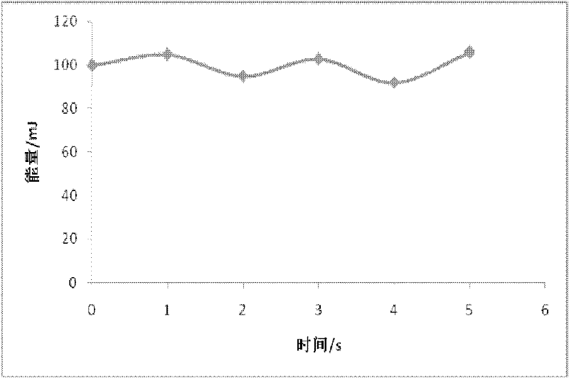
The laser energy output by the laser will fluctuate up and down with the instability of the injected laser energy. After the laser with unstable laser energy passes through some laser systems, this instability will even be amplified many times, so that the laser energy output by the laser The instability of the

Method used


Image

  • System and method capable of realizing energy stability of injected laser
  • System and method capable of realizing energy stability of injected laser
  • System and method capable of realizing energy stability of injected laser

Examples


Embodiment Construction

[0053] like figure 2 As shown, an embodiment of the present invention proposes a system for stabilizing injected laser energy, which is connected to an external injection fiber 1. The system includes: a first light splitting unit 3, a λ / 2 wave plate 4, a second light splitting unit 5, a delay The device 6, the energy monitoring device 9, the optical rotation device 7, the third spectroscopic unit 8 and the electric control device 10 connected to the optical rotation device 7 for controlling the optical rotation device 7, wherein:

[0054] The first light splitting unit 3 is configured to receive input light injected into the optical fiber from outside, and convert the input light into first horizontal linearly polarized light.

[0055] The λ / 2 wave plate 4 is used to receive the first horizontal linearly polarized light and rotate the first horizontal linearly polarized light by a predetermined angle θ.

[0056] The second light splitting unit 5 is used for receiving the rotat...


PUM


Abstract

The invention relates to a system and a method capable of realizing energy stability of injected laser. The system is connected with an external injection fiber and comprises a first light split unit, a Lambda / 2 wave plate, a second light split unit, an energy monitoring device, a delay device, an optical rotation device, a third light split unit and an electric control device, wherein the input light from the injection fiber is changed to a first horizontal polarized light by the first light split unit, is rotated at a preset angle Theta by the Lambda / 2 wave plate and is then split into a first polarized light and a second polarized light by the second light split unit, the first polarized light enters the energy monitoring device, the delay device receives and transmits the second polarized light in a delayed manner, the electric control device receives the energy E monitoring of the first polarized light and generates an optical rotation angle Beta according to the energy E monitoring, and the optical rotation device carries out optical rotation according to the angle Beta; and the third light split unit receives the second polarized light after optical rotation and outputs a second horizontal polarized light. According to the system and the method, the stability of pulse laser outputted by the system along with the time change is ensured, and the stable gain of the laser pulse is further realized.

Description

technical field [0001] The invention relates to the technical field of laser applications, in particular to a system and method for stabilizing injected laser energy by using electro-optic crystals. Background technique [0002] The electro-optic switch is a very important device in lasers. Its application is an important breakthrough in the history of laser development. It improves the monochromatic brightness of lasers by several orders of magnitude, and also promotes laser ranging, laser radar, and high-speed holography. And the development of application technology such as laser processing. The principle is to use the action of an external electric field to periodically change the refractive index of the crystal: under the action of an electric field, the uniaxial crystal periodically changes into a biaxial crystal, or the shape and orientation of the refractive index ellipsoid of the biaxial crystal change. Periodic change, the electro-optic switch causes the light pas...

Claims


Application Information

Patent Timeline
Patent Type & Authority Applications(China)
IPC IPC(8): H01S3/131
Inventor 樊仲维邱基斯唐熊忻侯立群
Owner BEIJING GK LASER TECH
Learn More