
Power switch driver, IC chip, and DC-DC converter

A power switch and driver technology, applied in the direction of output power conversion device, DC power input conversion to DC power output, instruments, etc.

Active Publication Date: 2012-07-04
WUXI ZGMICRO ELECTRONICS CO LTD
View PDF4 Cites 6 Cited by
  • Summary
  • Abstract
  • Description
  • Claims
  • Application Information

AI Technical Summary

Problems solved by technology

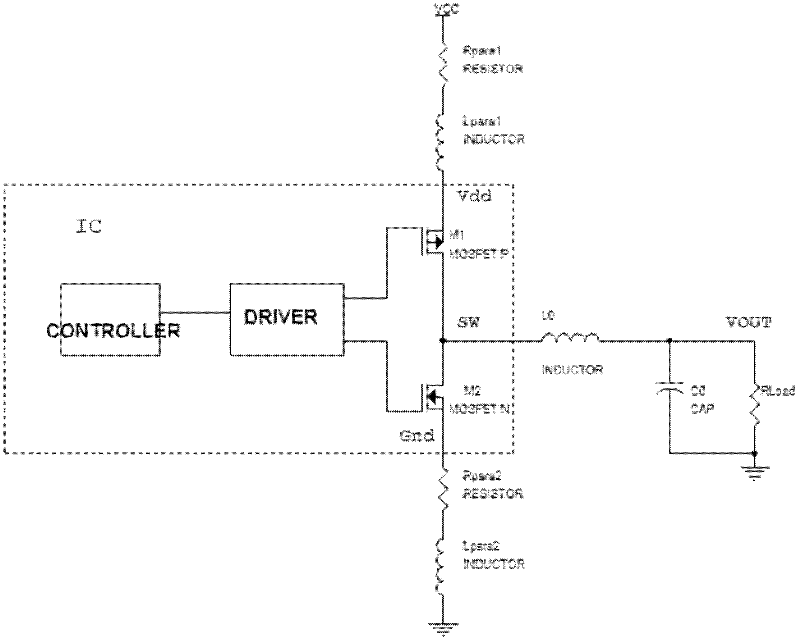
[0007] To sum up, the ground bounce phenomenon of the power switch in the prior art is relatively serious

Method used


Image

  • Power switch driver, IC chip, and DC-DC converter
  • Power switch driver, IC chip, and DC-DC converter
  • Power switch driver, IC chip, and DC-DC converter

Examples


Embodiment Construction

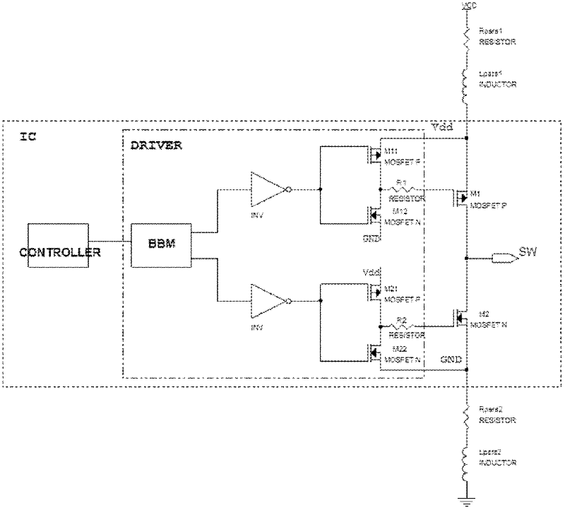
[0019] An embodiment of the present invention provides a power switch driver, an IC chip and a DC-DC converter, which are used to reduce the ground bounce of the switching power supply, and reduce the power switch off while maintaining a relatively slow turn-on speed of the power switch. When the grid of the power switch is connected to the power supply or ground impedance, the power switch after it is turned off cannot be turned on instantaneously through the coupling of parasitic capacitance.

[0020] see Figure 5 , a power switch driver (DRIVER) provided by an embodiment of the present invention includes NMOS M12 and PMOS M11 for controlling P-type power switch M1, and PMOS M21 and NMOS M22 for controlling N-type power switch M2. Switch drivers also include:

[0021] The first resistor R12 is connected between the source of the NMOS M12 and ground (GND); and,

[0022] The second resistor R21 is connected between the source of the PMOS M21 and the anode (Vdd) of the power...


PUM


Abstract

The invention discloses a power switch driver, an IC chip and a DC-DC converter, for lowering ground bounce of a switch power source and for lowering impedance from the gate of a power switch to the power source or the ground when the power switch is switched off while ensuring a low opening speed of the power switch so as to prevent instant-on of the power switch through coupling of a parasitic capacitor. The power switch driver provided by the invention comprises an N-channel metal oxide semiconductor field effect transistor NMOS for controlling a P-type power switch, and a P-channel metal oxide semiconductor field effect transistor PMOS for controlling an N-type power switch, and also includes a first resistor connected with source of the NMOS, and a second resistor connected with source of the PMOS.

Description

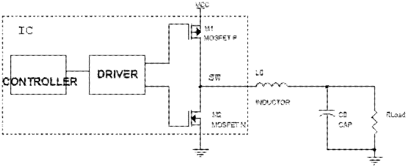
technical field [0001] The invention relates to the technical field of switching power supplies, in particular to a power switch driver, an IC chip and a DC-DC converter. Background technique [0002] The demand for portable devices and mobile communication systems is increasing day by day. These systems are inseparable from power supply systems. DC-DC converters (DC / DC Converters) are widely used due to their high efficiency. figure 1 Shown is a common synchronous step-down DC-DC converter (Buck, Step-Down DC / DCConverter) application circuit, including DC-DC converter integrated circuit (IC) chip, inductor L0, output capacitor C0 and load RLoad. Wherein, the IC chip includes a controller (CONTROLLER), a power switch driver (DRIVER), and power switches M1 and M2. [0003] The controller uses a certain control method (PWM or PFM) to generate a pulse control signal with a certain duty cycle (duty cycle), and drives the power switches M1 and M2 through the driver, so that the ...

Claims


Application Information

Patent Timeline
IPC IPC(8): H02M1/088H02M3/155
Inventor 杨喆王钊
Owner WUXI ZGMICRO ELECTRONICS CO LTD
Learn More