Offset printing method and device

A technology of offset printing and placing table, applied in the directions of printing devices, printing, printing machines, etc., can solve the problems of substrate printing accuracy, reduced reproducibility, undisclosed, unrealistic, etc., to prevent the deviation of printing accuracy and reproducibility , The effect of suppressing overlapping dislocation and overlapping dislocation

Inactive Publication Date: 2012-07-04
IHI CORP
View PDF11 Cites 10 Cited by
  • Summary
  • Abstract
  • Description
  • Claims
  • Application Information

AI Technical Summary

Problems solved by technology

However, it does not disclose any idea of ​​keeping the contact pressure of the roller to the plate and the contact pressure of the roller to each substrate whose thickness dimension is not necessarily constant.
Therefore, in the method disclosed in Patent Document 4, the possibility of a difference in the contact pressure between the cylinder and the plate or the substrate as mentioned above cannot be eliminated.
Moreover, the following problems cannot be eliminated: because of the difference in contact pressure when the roller contacts the plate or the substrate, there is a difference in the amount of change in the roll diameter of the contact portion between the roller and the plate or each substrate, and the peripheral speed of the contact portion changes. , so that the printing accuracy and reproducibility of each substrate are reduced
However, it is impractical to use plates or printing objects that are exposed from the rubber roller to the outside in the direction of the roller axis.
[0032] Furthermore, even if the planar plate or printing object is exposed from the squeegee to the outside in the direction of the roller axis and the thickness change of the exposed portion is measured, it is impossible to detect the difference between the flat plate or the printing object and the squeegee roller from the measurement results. Thickness change in the roll axis direction of the contact part

Method used


Image

  • Offset printing method and device
  • Offset printing method and device
  • Offset printing method and device

Examples


Embodiment Construction

[0090] Hereinafter, modes for implementing the present invention will be described with reference to the drawings.

[0091] Figures 1 to 11B One embodiment of the offset printing method and apparatus of the present invention is shown, and has the following configurations.

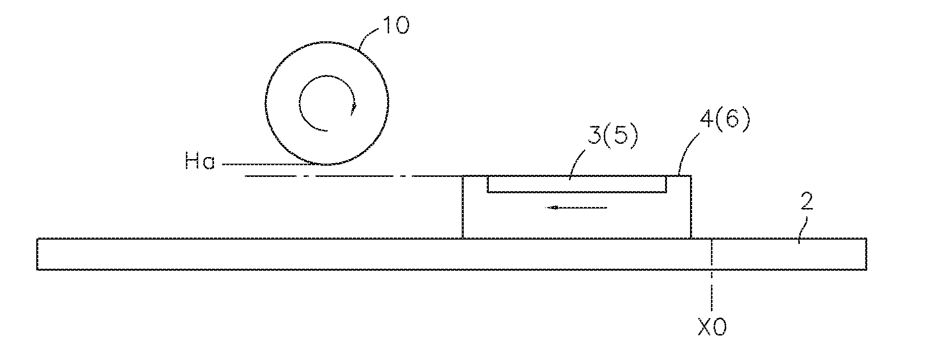
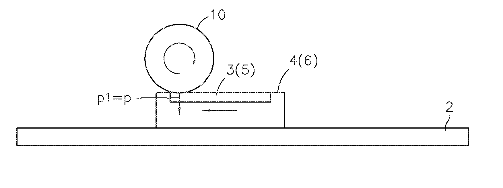
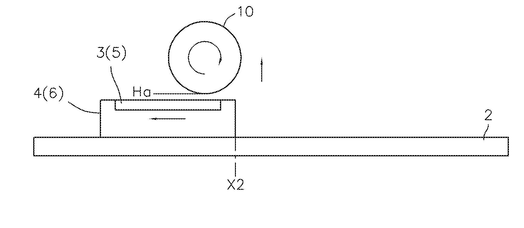
[0092]That is, on the upper side of the horizontal pedestal 1 , there are provided guide rails 2 extending in one direction (X-axis direction), for example, a set of two guide rails 2 . On the guide rail 2, sequentially from one end side in the length direction of the guide rail 2 ( figure 1 The left side in the figure) are disposed with a plate mounting table 4 holding a plate 3 such as an intaglio plate on its upper surface, and a substrate mounting table 6 as a printing object mounting table holding a printing target substrate 5 on its upper surface. These mounting tables 4 , 6 are mounted so as to be slidable with respect to the guide rail 2 via independent guide blocks 2 a , and independently move (...


PUM


Abstract

Disclosed is an offset printing device in which a printing-plate table (4) and a base-plate table (6) are movably provided on a guide rail (2) which is provided on a stand (1). A transfer mechanism (9) is provided at a location on the guide rail (2) corresponding to an intermediate section thereof in the longitudinal direction, the transfer mechanism (9) comprising: a blanket roll (10); a blanket roll raising / lowering actuator (13); a blanket roll height sensor (14); and a pressure sensor (15) for detecting the contact pressure of the blanket roll with respect to a printing plate (3) or a base plate (5). Furthermore, a controller controls the raising / lowering actuator (13) in such a way that the contact pressure detected by the pressure sensor (15) when the blanket roll (10) contacts the printing plate (3) or the base plate (5) reaches a prescribed value. The contact pressure when transfer is performed from the printing plate (3) to the blanket roll (10) and the contact pressure when re-transfer is performed from the blanket roll (10) to the base plate (5) are both made uniform, whereby the amount of deformation of the portion which contacts the printing plate (3) or the base plate (5) is made uniform and the peripheral speeds are made equal. As a result, the printing precision can be improved.

Description

technical field [0001] The present invention relates to an offset printing method and apparatus used for finely printing an object to be printed with high printing accuracy when forming an electrode pattern on a substrate by printing. [0002] this application claims priority based on Japanese Patent Application No. 2009-208717 for which it applied to Japan on September 9, 2009, and uses the content here. Background technique [0003] As one of the printing techniques, there is offset printing, and among them, offset printing using gravure is widely known as a method in which ink is temporarily transferred (received) from an inked gravure to a rotating rubber roller, and then Retransfer (printing) of the ink from the squeegee to the printing object enables the above-mentioned intaglio printing pattern to be printed on the surface of the printing object with good reproducibility. [0004] In addition, in recent years, as a method of forming an electrode pattern (conductive p...

Claims


Application Information

Patent Timeline
Patent Type & Authority Applications(China)
IPC IPC(8): B41F3/54B41F3/56B41F3/84B41F17/14B41M1/10
CPCB41F3/56B41M1/06B41F3/54B41F17/14B41M1/10
Inventor 铃木俊太郎中村惠子松尾研吾河口纪仁
Owner IHI CORP
Why Eureka
Try Eureka