In-wheel motor drive device

A hub motor and driving device technology, which is applied in the direction of electric power devices, gear transmission devices, electromechanical devices, etc., can solve problems such as the need for cooling water, the weight increase of the hub motor drive device, and the deterioration of the followability of the suspension device, so as to reduce the Effect of unsprung weight and ride comfort improvement

Active Publication Date: 2012-07-04
NTN CORP
View PDF8 Cites 24 Cited by
  • Summary
  • Abstract
  • Description
  • Claims
  • Application Information

AI Technical Summary

Problems solved by technology

[0006] However, in the above-mentioned conventional in-wheel motor driving device, there is room for improvement as described below.
In other words, there are problems in that not only must a separate cooling water channel be provided, but also cooling water is required, the weight of the in-wheel motor drive device increases, and the followability of the suspension device deteriorates.

Method used


Image

  • In-wheel motor drive device
  • In-wheel motor drive device
  • In-wheel motor drive device

Examples


Embodiment Construction

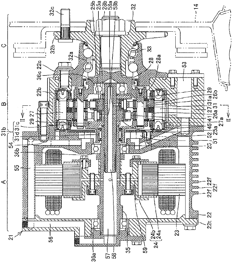
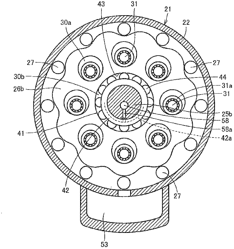
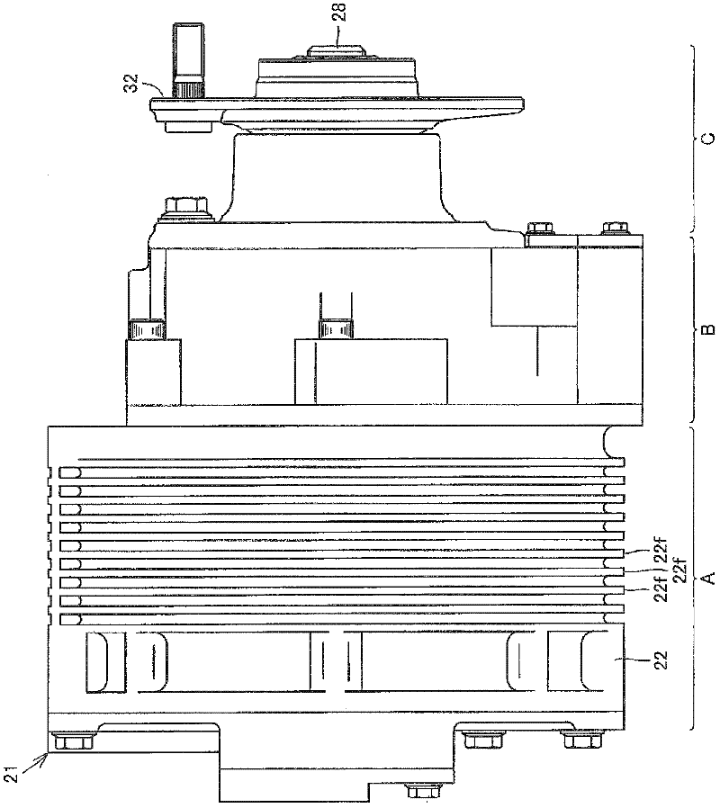
[0038] Hereinafter, embodiments of the present invention will be described in detail based on examples shown in the drawings. figure 1 It is a longitudinal sectional view showing the in-wheel motor driving device as the first embodiment of the present invention. figure 2 yes figure 1 Sectional view of II-II. image 3 yes figure 1 Side view of an in-wheel motor drive unit. Figure 4 is viewed from the axis figure 1 Front view of the in-wheel motor drive unit. Figure 5 is has figure 1 A top view of an in-wheel motor drive unit for an electric vehicle. Figure 6 yes Figure 5 Rear sectional view of an electric motor vehicle.

[0039] refer to Figure 5 , The electric vehicle 11 has: a chassis 12; a front wheel 13 as a steering wheel; a rear wheel 14 as a driving wheel; refer to Figure 6 The rear wheel 14 is housed inside the wheel house 12a of the chassis 12, and is fixed to the lower portion of the chassis 12 via a suspension device (suspension) 12b.

[0040] The ...


PUM


Abstract

An air-cooled, in-wheel motor drive device (21) is provided with a lubricating oil circuit which is configured in such a manner that a lubricating oil which is discharged from a lubricating oil pump (51) lubricates a reduction section (B) by flowing and circulating through oil paths (54, 55, 56) which are connected to each other and are provided in a casing (22), an oil path (57) which is provided in a motor's rotating shaft, an oil path (58) which is provided in the reduction section's input shaft, and the inside of the reduction section (B), and that the lubricating oil which flows through the oil paths (54, 55, 56), which are provided in the casing, and is cooled by outer peripheral fins (22f) cools a motor section (A) and the reduction section (B).

Description

technical field [0001] The present invention relates to an in-wheel motor drive device used as a power source of a vehicle, in which a rotating shaft of a motor is connected to a hub of a wheel via a reduction gear. Background technique [0002] A conventional in-wheel motor driving device is described in, for example, Japanese Unexamined Patent Publication No. 2009-63043 (Patent Document 1). The in-wheel motor drive device described in Patent Document 1 includes a motor unit, a deceleration unit, a wheel hub, and a deceleration unit lubricating mechanism for supplying lubricating oil to the deceleration unit. In addition, a cooling water channel and a radiator are provided in the casing of the motor unit. In addition, the motor unit is cooled by flowing cooling water through the cooling water passage. [0003] 【Prior technical literature】 [0004] 【Patent Literature】 [0005] [Patent Document 1] Japanese Unexamined Patent Publication No. 2009-63043 (page 8, first drawin...

Claims


Application Information

Patent Timeline
Patent Type & Authority Applications(China)
IPC IPC(8): B60K7/00F16H1/32F16N39/02H02K5/18H02K5/20H02K9/19
CPCB60K17/046F16H1/32H02K9/19B60K2007/0092B60K2007/0038B60K2001/003H02K1/32H02K7/14Y02T10/641H02K5/20B60K7/0007Y02T10/64H02K5/203
Inventor 牧野智昭山本宪
Owner NTN CORP
Why Eureka
Try Eureka