Device for the inductive transfer of electric energy

A technology of electric energy and sensors, applied in the direction of electrical devices, circuit devices, battery circuit devices, etc., can solve the problem that metal detectors are not adopted

Active Publication Date: 2012-07-04
CONDUCTIX WAMPFLER
View PDF8 Cites 35 Cited by
  • Summary
  • Abstract
  • Description
  • Claims
  • Application Information

AI Technical Summary

Problems solved by technology

In this document, the use of metal detectors was dismissed as useless despite mentioning the presence of metal foreign objects

Method used


Image

  • Device for the inductive transfer of electric energy
  • Device for the inductive transfer of electric energy
  • Device for the inductive transfer of electric energy

Examples


Embodiment Construction

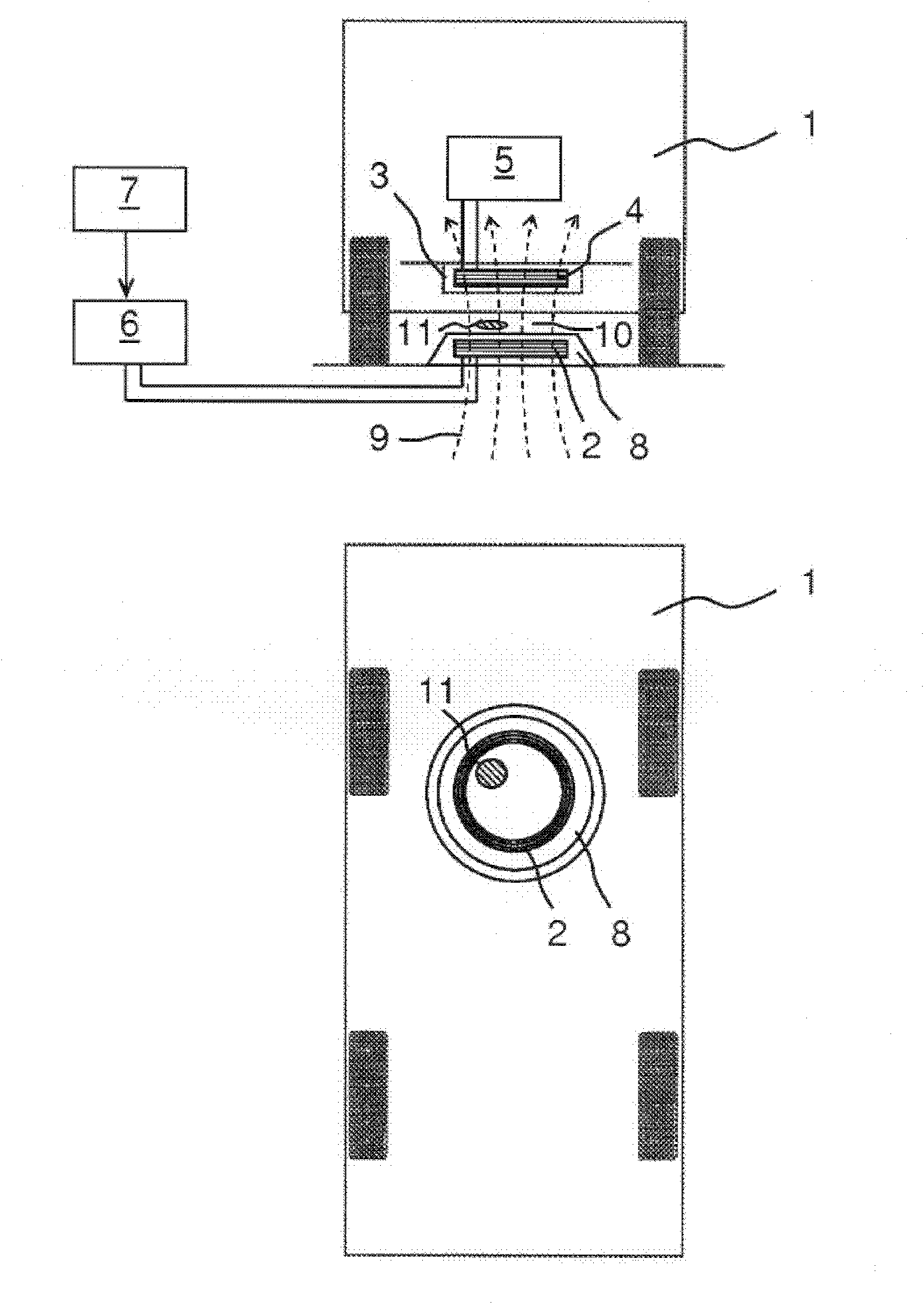
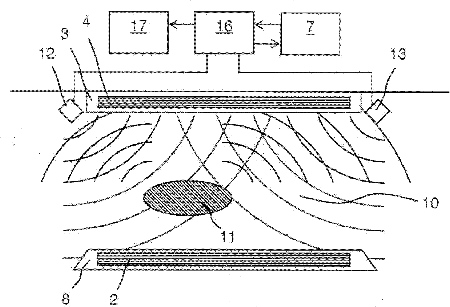
[0016] figure 1 An electric vehicle 1 is shown schematically in sectional view (top) and plan view (bottom), which is positioned above a primary coil 2 of a charging station for charging its battery. A secondary coil 4 connected to an electronic charging device 5 is located in a housing 3 on the underside of the vehicle 1 . This electronic charging device converts parameters of the electrical power induced into the secondary coil 4 into values ​​suitable for charging the battery of the vehicle 1 . The primary coil 2 is supplied with power by a power supply unit 6 of the charging station and is accommodated in a housing 8 which is fixedly positioned on the parking space. The power supply unit 6 is controlled by a control unit 7 of the charging station.

[0017] exist figure 1 Several field lines 9 of the alternating magnetic field generated by the primary coil 2 during operation are shown in dotted lines. The main direction of this alternating magnetic field corresponds to ...


PUM


Abstract

The invention relates to a device for the inductive transfer of electric energy from a stationary unit comprising at least one primary inductance to a vehicle that is adjacent to said unit and has at least one second inductance. The stationary unit or the vehicle has a device for detecting the presence of an object in a predetermined area that covers at least the area lying between the primary inductance and the second inductance during the inductive energy transfer. The detection device has at least one contactless sensor and an evaluation unit that is connected to the sensor. At least the sensor of the detection device is integrated into or mounted on the same housing as the primary or secondary coil of the energy transfer device. The sensor can be an ultrasonic sensor, radar sensor, infra-red sensor or an electric image sensor.

Description

technical field [0001] The invention relates to a device for the inductive transfer of electrical energy according to the preamble of claim 1 . Such a device is used for the inductive charging of rechargeable batteries installed in electric vehicles. During power transmission, a magnetic field with high field strength and flux density is formed in the spatial region between the stationary primary coil and the vehicle-side secondary coil. The foregoing is necessary in order to induce a sufficiently high current in the secondary coil for the desired delivered power. Background technique [0002] If a person, human limb or animal enters the area, an electric current is induced through the body. Although it can be considered that generally this does not lead to immediate danger, especially if there is no need to worry about being in the area for an extended period of time. However, the acceptance of inductive power transfer in some populations is limited by the possibility of...

Claims


Application Information

Patent Timeline
Patent Type & Authority Applications(China)
IPC IPC(8): H02J7/00H02J7/02B60L11/18
CPCH02J7/025Y02T90/122B60L2270/147Y02T10/7088B60L3/0069B60L2240/36Y02T10/7005B60L11/1829Y02T90/14Y02T90/125B60L11/182Y02T90/12Y02T10/7072B60L53/38B60L53/124H02J50/10H02J50/60Y02T10/70B60L53/12B60Y2200/91
Inventor M·韦希林A·格林
Owner CONDUCTIX WAMPFLER
Why Eureka
Try Eureka