Device and method for feeding rare earth alloy during continuous casting process

A rare earth alloy and continuous casting technology, which is applied in the field of smelting, can solve the problems of uneven distribution of rare earth and sulfur, insufficient diffusion of rare earth, and late addition of rare earth, so as to achieve long melting and dissolution time, eliminate longitudinal crack defects, and improve internal quality effect

Inactive Publication Date: 2012-07-11
ANGANG STEEL CO LTD
View PDF3 Cites 2 Cited by
  • Summary
  • Abstract
  • Description
  • Claims
  • Application Information

AI Technical Summary

Problems solved by technology

But this method also has the following defects: 1. The rare earth addition time is late, the rare earth is not sufficiently diffused in the crystallizer, and there is no kinetic condition that can make the inclusions float, so the rare earth reaction products are mostly left in the steel and 2. The distribution of rare earth and sulfur on the slab section is uneven, which affects the application of this process in high-quality steel products and pure steel; 3. This method has a limit value requirement for the minimum thickness of the continuous casting slab. The application of medium slab will produce defects and lead to the scrapping of steel plate
[0005] So far, there is no record or report about adding rare earth alloys to molten steel through a tundish during continuous casting

Method used


Image

  • Device and method for feeding rare earth alloy during continuous casting process
  • Device and method for feeding rare earth alloy during continuous casting process

Examples


Embodiment 1

[0030] The inner diameter of the joint 1 is 10 mm, the outer diameter of the metal tee pipe 2 straight pipe and the inclined pipe are both 10 mm, and the angle between the straight pipe axis and the inclined pipe axis of the metal tee pipe 2 is 30°. A two-strand slab continuous casting machine is adopted, the cross-section of the slab is 1150×230 mm, and the casting speed is 1.2 m / min.

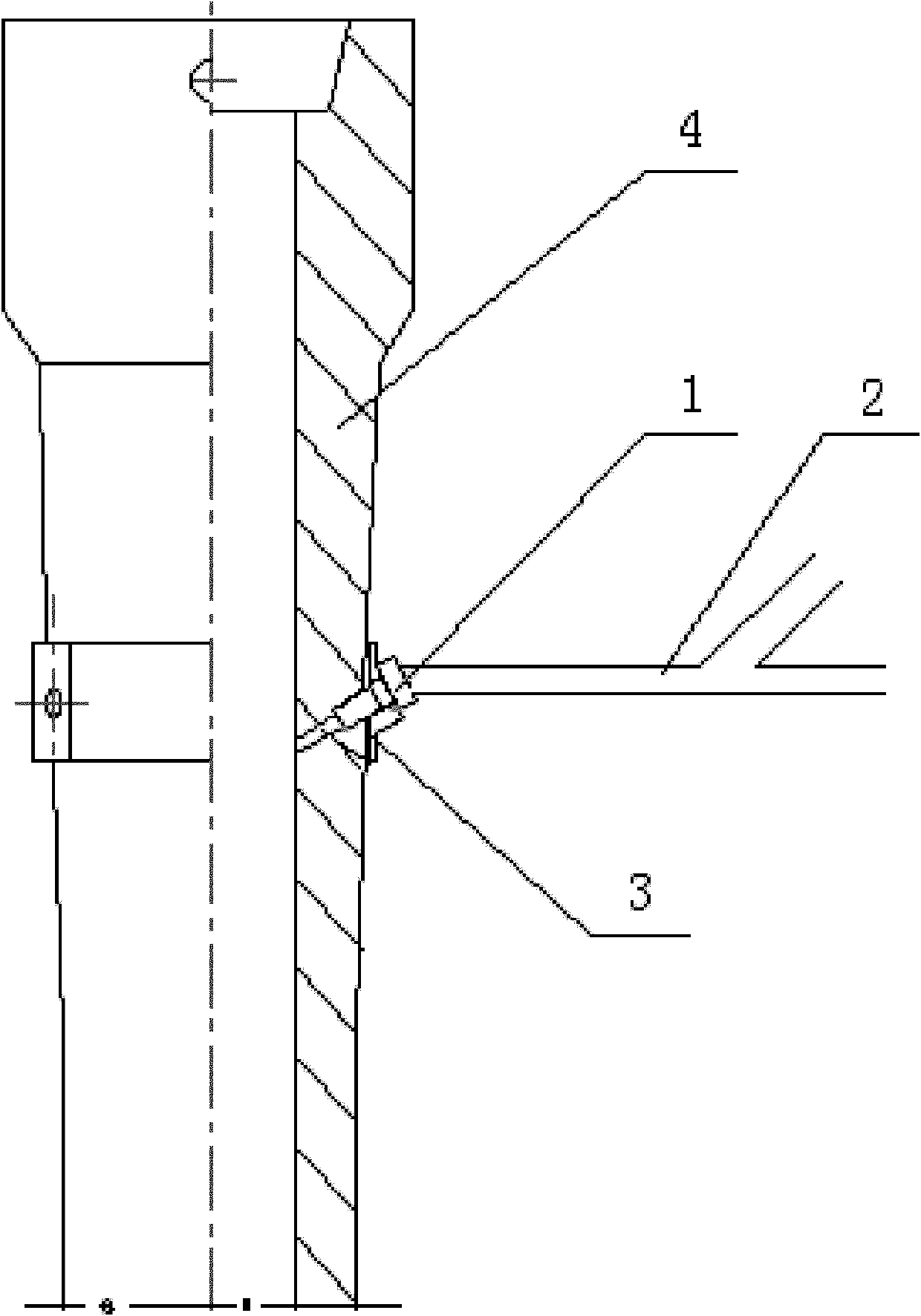
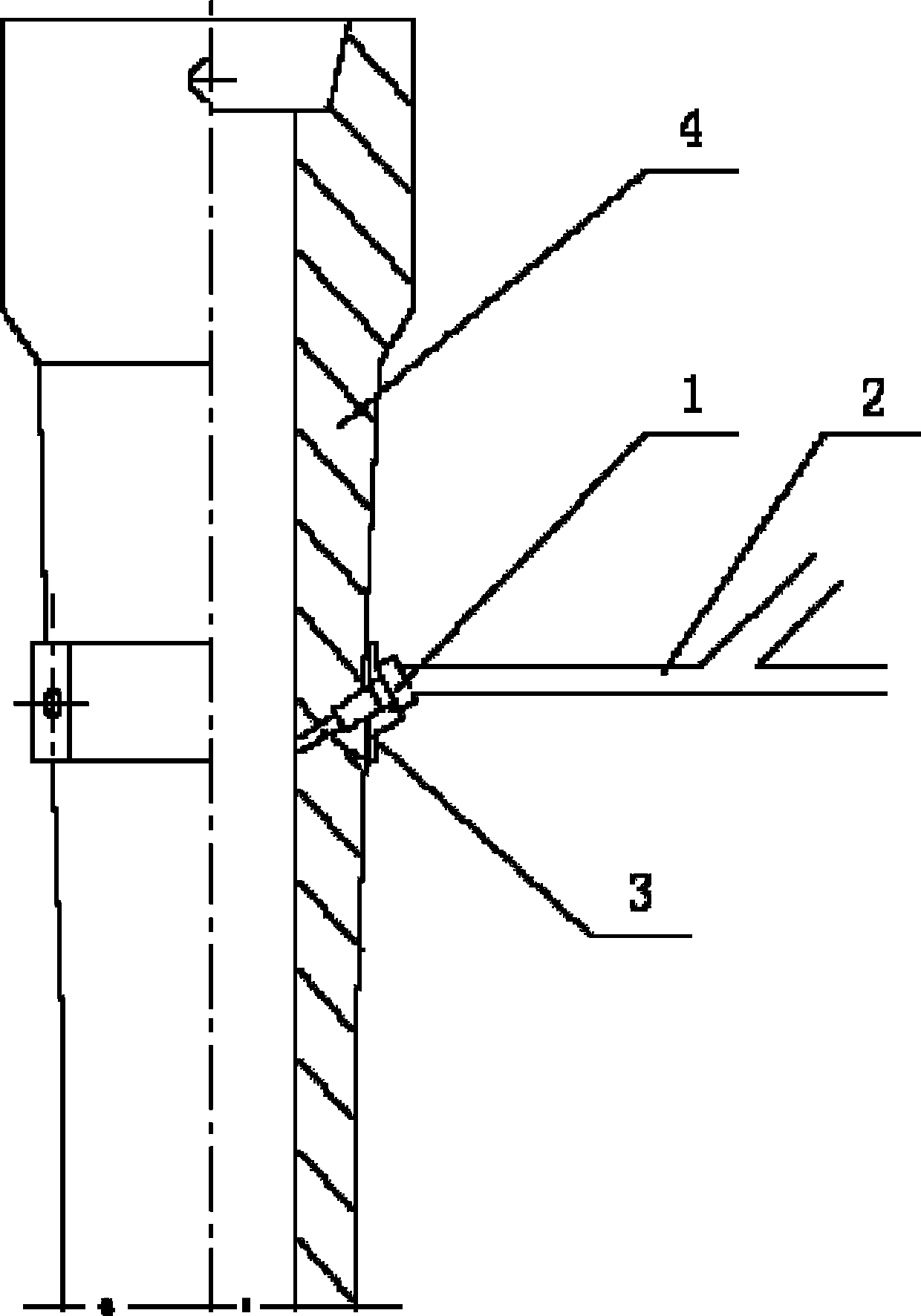
[0031] First, drilling and equipment connections are made. During the pouring process of the molten steel tank, two holes with a diameter of 13mm are symmetrically drilled with an electric drill along the radial direction of the outer wall of the long nozzle 4 of the tundish. The angle is 10°. Insert the lower parts of the joints 1 of the two pre-installed feeding devices into their respective holes, and fix the joints 1 together with the feeding devices on the outer wall of the shroud 4 through the clamp 3 .

[0032] Next, perform inert gas blowing and wire feeding. With a flow rate of 50 ...

Embodiment 2

[0034] The inner diameter of the joint 1 is 20 mm, the outer diameter of the metal tee pipe 2 straight pipe and the inclined pipe are both 20 mm, and the angle between the straight pipe axis and the inclined pipe axis of the metal tee pipe 2 is 120°. A two-strand slab continuous casting machine is used, the section of the slab is 1150×230 mm, and the casting speed is 1.0 m / min.

[0035] First, drilling and equipment connections are made. During the pouring process of the molten steel tank, 8 holes with a diameter of 24 mm are drilled downward in a spiral shape at a distance of 200 mm from the upper end of the shroud 4 with an electric drill, and the included angle between the axis of the holes and the axis of the shroud 4 is 50°. Insert the lower parts of the joints 1 of the 8 pre-installed feeding devices into their respective holes, and fix all the joints 1 together with the feeding devices on the outer wall of the shroud 4 through clamps 3 .

[0036] Next, perform inert ga...

Embodiment 3

[0038] The inner diameter of the joint 1 is 30 mm, the outer diameter of the straight pipe and the inclined pipe of the metal tee pipe 2 are both 30 mm, and the angle between the straight pipe axis and the inclined pipe axis of the metal tee pipe 2 is 150°. A two-strand slab continuous casting machine is adopted, the cross-section of the slab is 1150×230 mm, and the casting speed is 1.0 m / min.

[0039] During the pouring process of the steel ladle, 5 holes with a diameter of 35mm were irregularly drilled downward with an electric drill at a distance of 500 mm from the upper end of the shroud 4, and the angle between the axis of the holes and the axis of the shroud 4 was 75°. Insert the lower parts of the joints 1 of the five pre-installed feeding devices into their respective holes, and fix all the joints 1 together with the feeding devices on the outer wall of the shroud 4 through clamps 3 .

[0040] With a flow rate of 20 L / min and an air pressure of 11 atm, Ar and N are blo...


PUM

PropertyMeasurementUnit
diameteraaaaaaaaaa

Abstract

The invention provides a device and a method for feeding rare earth alloy during continuous casting process. The method comprises drilling a hole at a shroud wall of a tundish during the molten steel casting process, inserting a joint connected with a metal three-way pipe into the hole, blowing inert gas into the inclined tube of the metal three-way pipe, running the rare earth alloy cored wire under the protection of the inert gas through the metal three-way pipe and the joint, and feeding into the molten steel by a wire feeder. The rare earth fed by the invention is uniformly distributed in the molten steel, the formed small impurities are likely to aggregate and float, the sulfide modification effect is remarkable; the columnar crystal and the segregation region are smaller, so that the molten steel is purified effectively. Synchronously, the roll residue within 1 / 4 range of inner arc of the continuously cast plate blank and the vertical fracture defect of the plate are avoided, the danger of steel leakage during the rare earth feeding process of the crystallizer is absolutely avoided. The addition of the rare earth can be optionally adjusted. In this way, requests of adding rare earth by various continuous casting width-thickness ratio plates and advanced rolling technology are satisfied.

Description

technical field [0001] The invention belongs to the technical field of smelting, and in particular relates to a device and method for adding rare earth alloys into a tundish during continuous casting. Background technique [0002] The role of rare earths in steel and metal materials has attracted increasing attention and has been widely used. This is because adding rare earths to steel has the following effects: 1. Purifying molten steel. Adding rare earth to steel is easy to form large-grained rare earth composite inclusions with low melting point. Such inclusions have a large specific surface tension with molten steel and are easy to float and discharge; The properties, morphology, quantity, size and distribution of carbides and non-metallic inclusions; 3. Microalloying, that is, solid solution, solid solution rare earth can solidify grains and purify grain boundaries, which can not only improve the strength of materials Toughness, but also improve the corrosion resistan...

Claims


Application Information

Patent Timeline
Patent Type & Authority Applications(China)
IPC IPC(8): B22D11/108B22D11/11
Inventor 唐复平李镇王晓峰林洋吴春杰孙涛费鹏姜振生陈本文康伟栗红孙群辛国强王荣
Owner ANGANG STEEL CO LTD
Why Eureka
Try Eureka