Welding torch, welding tip, and welding robot

A welding tip and welding torch technology, applied in welding equipment, electrode characteristics, arc welding equipment, etc., can solve the problems of screw crushing, difficulty in increasing or decreasing force of welding tip for disassembly and assembly, and insufficient simplification of disassembly and assembly operations. , to achieve the effect of easy disassembly and assembly and elimination of welding tip sticking

Active Publication Date: 2012-07-11
KOBE STEEL LTD
View PDF5 Cites 6 Cited by
  • Summary
  • Abstract
  • Description
  • Claims
  • Application Information

AI Technical Summary

Problems solved by technology

Therefore, when detaching the welding tip, it is necessary to rotate the screw, which is not sufficient in terms of simplification of detachment work.
In addition, copper with high electrical conductivity is usually used for the components of the welding torch, but copper is relatively soft, so the thread teeth of the screw may be crushed, and the welding tip cannot be properly fixed.
[0012] In addition, with the technology disclosed in Japanese Patent Application No. 2005-144548, it is very difficult to increase or decrease the force when disassembling the welding tip, and at the same time, it is necessary to remove the O-ring and spring separately, as disclosed in Japanese Patent Application No. 60-38673 Both technologies require complex actions such as rotating the screw when disassembling the welding tip. Therefore, neither technology is suitable for the automation of welding tip disassembly.

Method used


Image

  • Welding torch, welding tip, and welding robot
  • Welding torch, welding tip, and welding robot
  • Welding torch, welding tip, and welding robot

Examples


Embodiment

[0115] Next, the results of welding using a welding torch (Example) having a specified configuration according to the present invention are compared with the results of welding using a conventional welding torch (Comparative Example) not having a specified configuration according to the present invention. The welding torch of the present invention.

[0116]

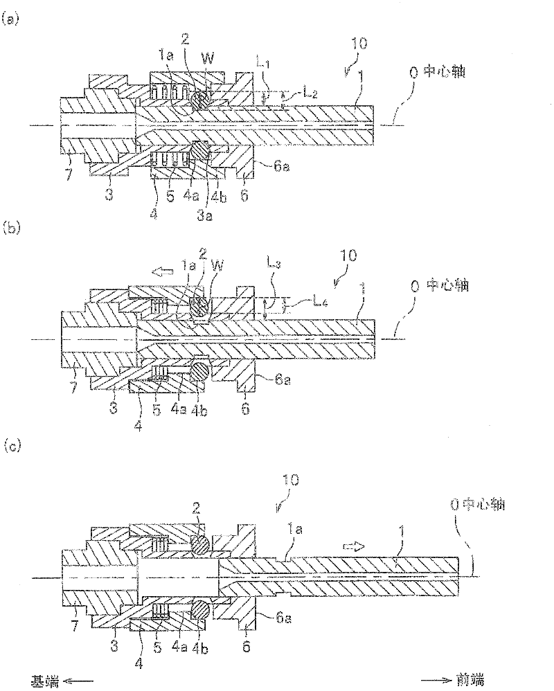
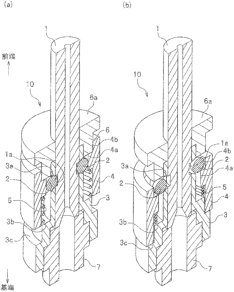
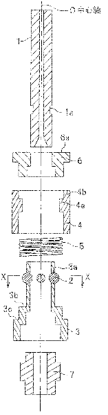
[0117] The welding torch of embodiment is as figure 1 As shown, it consists of a welding tip forming a fixing groove, a welding tip connecting body forming a fixing hole, a holding member forming a diameter-reducing part and a diameter-expanding part, an elastic member, a spherical fixing member, a ring-shaped sealing member and Connection components.

[0118] On the other hand, the welding torch of the comparative example is composed of a welding tip having an external thread formed on the outer peripheral surface of the base end portion and a tip connecting body having an internal thread formed on the inner periphera...


PUM


Abstract

A welding torch includes a tip connection body, a holding member, a fixing member, and a welding tip. The holding member is displaceable in the axial direction of the tip connection. The fixing member fixes the welding tip in place in the axial direction of the welding tip when the fixing member is in contact with a smaller diameter portion, and the fixing member releases the welding tip when the fixing member is in contact with a larger diameter portion. With such configuration, the operation of attaching and removing a welding tip is simplified, the problem of tip fusion is solved, and that is suitable for automating the operation of attaching and removing a welding tip.

Description

technical field [0001] The invention relates to a welding torch for gas shielded arc welding, a welding tip and a welding robot. Background technique [0002] Generally, in gas shielded arc welding, a consumable copper electrode called a contact tip (hereinafter referred to as a welding tip) is used as a power feeding member for feeding power to a welding wire. A through hole is formed in the welding tip, and the welding wire is continuously fed into the through hole, and at the same time, a current is passed through the welding wire through the welding tip, whereby the welding wire coming out from the tip of the welding tip and the welding base material arc occurs between them. [0003] When gas-shielded arc welding is performed, the inner peripheral surface of the through hole at the tip of the welding tip rubs against the welding wire, and this part is worn away. As a result, the inner diameter of the through hole increases, causing deviation of the welding position and...

Claims


Application Information

Patent Timeline
Patent Type & Authority Applications(China)
IPC IPC(8): B23K9/26B23K9/28B23K9/16
CPCB23K9/295B23K9/123B23K9/173B23K9/26B23K9/29
Inventor 泉谷瞬铃木励一
Owner KOBE STEEL LTD
Why Eureka
Try Eureka