Metal pipe welding method and metal pipe welding assembly

A technology of metal pipe fittings and welding methods, which is applied in the field of metal pipe fitting welding components, can solve problems such as burn-through, low connection strength, and affect service life, and achieve the effect of preventing tumor hanging and improving weld strength

Inactive Publication Date: 2012-07-11
浙江天力久田管业有限公司
View PDF8 Cites 30 Cited by
  • Summary
  • Abstract
  • Description
  • Claims
  • Application Information

AI Technical Summary

Problems solved by technology

[0003] The socket welding connection method is to insert the welding end of a pipe fitting to be welded into the lumen of the welding end of another pipe fitting to be welded and then weld it. See figure 1 As shown, it has the following disadvantages: (1) The connection strength is low; the socket welding connection is a lap connection, and its weld seam is a fillet weld seam, and the working stress is shear stress. According to the allowable strength The calculation method, and the effective load-bearing area of ​​the fillet weld is 0.707 times the effective area of ​​the fillet weld. Therefore, when designing the lap weld, double-sided welding is required to make the weld strength and the component (generally pipe A and joint fitting B) equal intensity
For the socket connection between pipes and pipe fittings, in actual construction, only one side welding can be carried out on one side of the pipe fittings, and the end of the pipe inserted into the pipe fittings cannot be welded, so the weld strength of the socket connection joint can only reach the strength of the pipe 50% of
(2) Welding is difficult, and it is easy to weld through the pipe wall. The pipe must be inflated for protection and socket welding. Because the pipe inser

Method used


Image

  • Metal pipe welding method and metal pipe welding assembly
  • Metal pipe welding method and metal pipe welding assembly
  • Metal pipe welding method and metal pipe welding assembly

Examples


Embodiment 1

[0038] (Example 1, metal pipe fitting welding assembly and welding method thereof)

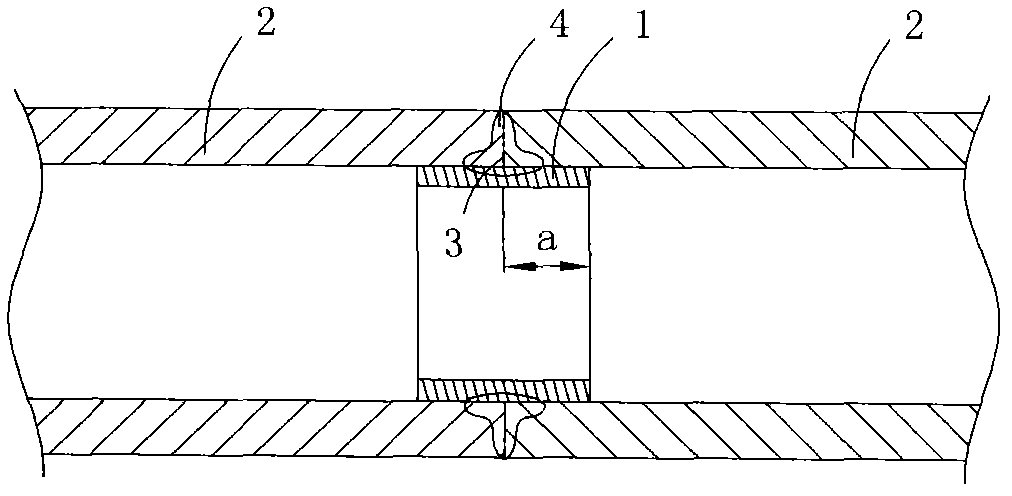
[0039] image 3 It is a structural schematic diagram of the first structure of the metal pipe fitting welding assembly in the present invention, showing the first specific embodiment of the present invention.

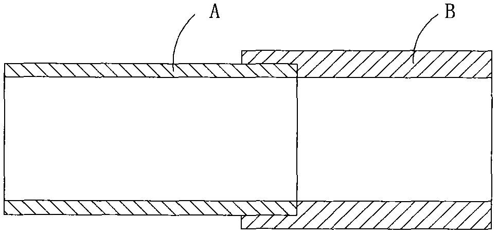
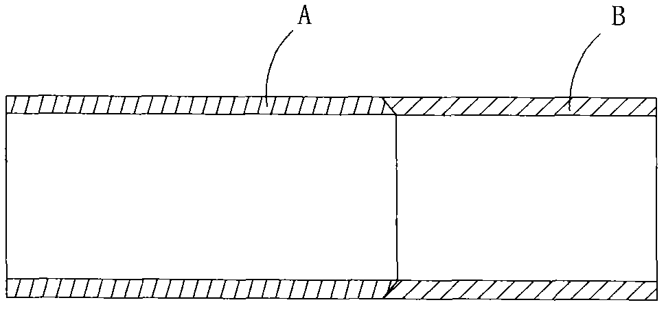
[0040] This embodiment is a welded assembly of stainless steel thin-walled pipe fittings, see figure 1 As shown, it includes two welded pipes 2 and a liner 1, the two ends of the liner 1 are respectively inserted into the lumen of the welded end of a welded pipe, and the butt joint of the welded ends of the two welded pipes has a welding process formed Melting zone 4.

[0041] In this embodiment, before welding, the liner 1 is fixed in the lumen of the pipe to be welded by a tight fit, and after welding, the part of the liner 1 adjacent to the butt joint of the two pipes to be welded is also melted , and form the melting zone 4 together with the butt welds of the welding ends of the ...

Embodiment 2

[0057] (Example 2, metal pipe fitting welding assembly and welding method thereof)

[0058] Figure 4 It is a structural schematic diagram of the second structure of the metal pipe fitting welding assembly in the present invention, showing the second specific embodiment of the present invention.

[0059] This embodiment is basically the same as Embodiment 1, the difference is: the two pipe fittings to be welded in this embodiment, one of them is a stainless steel pipe, the other is a pipe joint, and the pipe joint can be a two-way, three-way, or bent Equal pipe joints; the shape of the axial cross-section of the seam 3 to be welded is oblique at an angle to the central axis of the pipe to be welded 2 , which results in a different shape of the final fusion zone 4 .

Embodiment 3

[0060] (Example 3, metal pipe fitting welding assembly and welding method thereof)

[0061] Figure 5 It is a structural schematic diagram of the third structure of the metal pipe fitting welding assembly in the present invention, showing the third specific embodiment of the present invention.

[0062] This embodiment is basically the same as Embodiment 1, except that the two pipes to be welded in this embodiment are not thin-walled stainless steel pipes, but ordinary stainless steel pipes with normal thickness. The axial cross-sectional shape of the to-be-welded seam 3 is a semi-elliptical shape perpendicular to the central axis of the to-be-welded pipe 2 , thus resulting in a different shape of the final fusion zone 4 .


PUM


Abstract

The invention discloses a metal pipe welding method and a metal pipe welding assembly. The method comprises the steps of: (1) inserting one end of a liner tube into the pipe cavity at the welded end of a pipe to be welded in such a manner that the other end of the liner tube protrudes out of the welded end of the pipe to be welded; (2) inserting the portion of the liner tube protruding out of the welded end of the pipe to be welded into the pipe cavity of the welded end of another pipe to be welded, and butt-connecting the welded ends of the two pipes to be welded to form a seam to be welded; and (3) welding the pipes at the seam to be welded to form a fusion region so as to connect the welded ends of the two pipes to be welded. The metal pipe welding assembly comprises two pipes to be welded and a liner tube, wherein both ends of the liner tube are respectively inserted in the pipe cavity of one pipe to be welded; and a fusion region is formed by welding at the joint of the welded ends of the two pipes to be welded. During conducting gas shielded welding, the metal pipe welding method can ensure the final welding seam strength equal to the strength of the two pipes at both ends without filling the inner side of the welding seam with a protective gas, and can effectively prevent occurrence of hanging accretions.

Description

technical field [0001] The invention belongs to the technical field of metal pipe welding connection, and in particular relates to a metal pipe welding method and a metal pipe welding assembly made by the method. Background technique [0002] The safest and most reliable connection method among metal pipe connection methods is undoubtedly the welding connection. However, several existing connection methods such as socket welding connection or butt welding connection have certain defects, especially for the welding of thin-walled stainless steel pipes. [0003] The socket welding connection method is to insert the welding end of a pipe fitting to be welded into the lumen of the welding end of another pipe fitting to be welded and then weld it. See figure 1 As shown, it has the following disadvantages: (1) The connection strength is low; the socket welding connection is a lap connection, and its weld seam is a fillet weld seam, and the working stress is shear stress. Accordin...

Claims


Application Information

Patent Timeline
IPC IPC(8): B23K31/02B23K33/00F16L13/02B23K101/06
Inventor 阮继成阮懋
Owner 浙江天力久田管业有限公司
Why Eureka
Try Eureka