
Annealing method for hollow rolled object

A roll-shaped, hollow technology, applied in furnaces, heat treatment equipment, heat treatment furnaces, etc., can solve the problems of poor annealing effect, large energy waste, and long annealing time of the annealing furnace for hollow rolls, and shorten the annealing time and temperature. Uniformity, the effect of improving heat transfer efficiency

Inactive Publication Date: 2012-07-11
SNTO TECH GRP
View PDF2 Cites 1 Cited by
  • Summary
  • Abstract
  • Description
  • Claims
  • Application Information

AI Technical Summary

Problems solved by technology

Therefore, the annealing time of the existing annealing furnace is long, the production efficiency is low, and the energy waste is large; and the annealing effect of the hollow roll is poor, and the quality is unstable

Method used


Image

  • Annealing method for hollow rolled object
  • Annealing method for hollow rolled object
  • Annealing method for hollow rolled object

Examples


Embodiment 1

[0024] Embodiment one, see figure 1 and figure 2

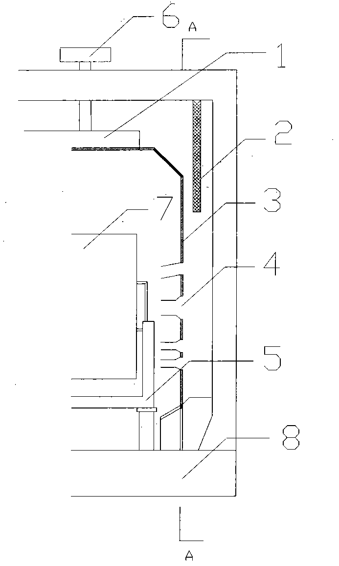
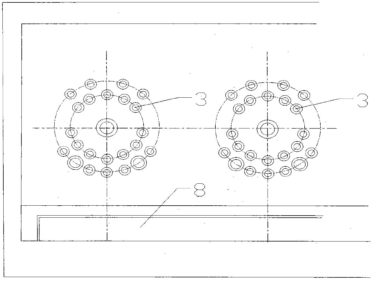
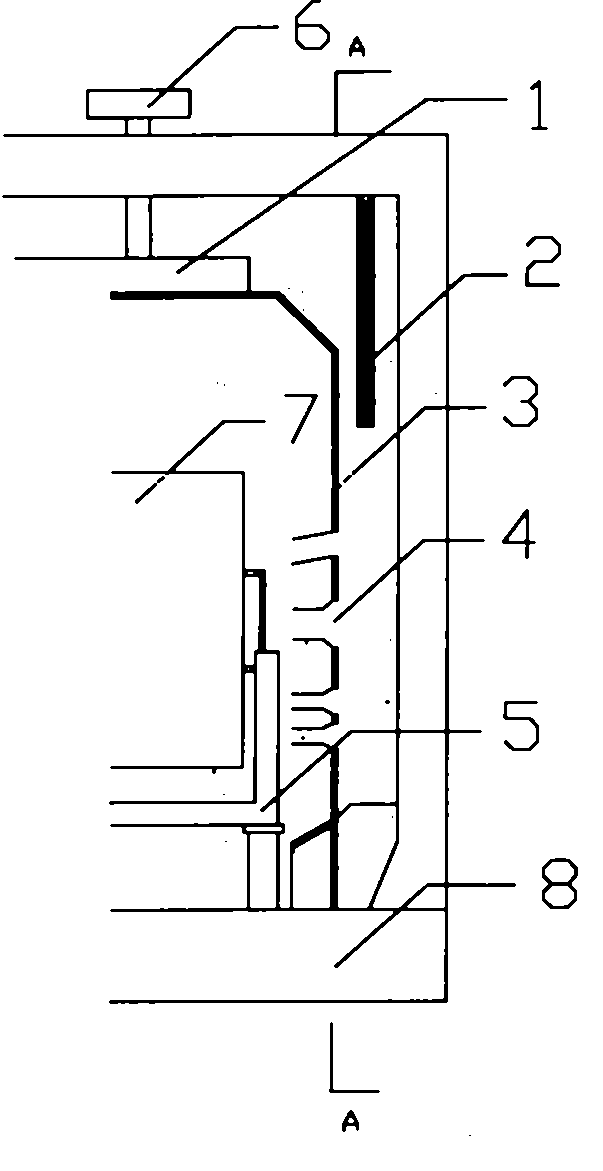
[0025] Step 101: Place the hollow roll 7 horizontally on one side of the deflector 3, and the deflector 3 is provided with at least two nozzles 4 with different diameters; the nozzles 4 are arranged as at least two concentric circles array.

[0026] A hollow roll support member 5 is provided on one side of the deflector 3 , and the hollow roll 7 is horizontally placed on the hollow roll support member 5 with its roller axis parallel to the ground.

[0027] The caliber of the nozzle 4 is different, and the high-temperature airflow can be purposefully and targetedly introduced into the weak points of the traditional heating method, such as the core of the hollow roll, the upper side of the hollow roll, etc., thereby accelerating the hollowing process. The time for each part of the roll to reach the temperature of the oven. Therefore, nozzles 4 with larger diameters can be arranged on the deflector 3 at positions correspondi...

Embodiment 2

[0033] Step 201: Place the first hollow roll 7 horizontally on one side of the deflector 3, the height of the centerline of the roller shaft of the first hollow roll is the same as the height of the nozzle at the center of the first concentric circle array unanimous.

[0034] Step 202: Place the second hollow roll 7 laterally on one side of the deflector 3, the height of the centerline of the roller axis of the second hollow roll is the same as the height of the nozzle at the center of the second concentric circle array unanimous.

[0035] If there is also a third concentric circle array and a fourth concentric circle array on the deflector 3, the third hollow roll and the fourth hollow roll can also be horizontally placed on the guide plate according to steps 201 and 202. Flow plate 3 side.

[0036] The height of the nozzle located at the center of the concentric circle array is the same as the height of the centerline of the hollow roll roller, so that the nozzle located a...


PUM


Abstract

The invention discloses an annealing method for a hollow rolled object. The annealing method comprises the following steps of: horizontally placing the hollow rolled object on one side of a guide plate; arranging at least two sprayer pipes with different apertures on the guide plate; arraying the sprayer pipes into an array composed of at least two concentric circles; and starting a heating part and a fan, wherein an air outlet of the fan is located above the hollow rolled object and on the same side of the guide plate. According to the annealing method, air around the hollow rolled object is circulated in the manner of ascending central bottom and descending two sides and the airflow can directly reach a core part of the hollow rolled object through the sprayer pipes on the lateral guide plate, so that the traditional single radial heating mode is changed, the time for reaching consistent temperature inside and outside the hollow rolled object is shortened, the energy source is saved and the annealing quality of the hollow rolled object is improved.

Description

technical field [0001] The invention relates to the technical field of annealing metal hollow rolls, in particular to an annealing method for hollow rolls. Background technique [0002] Annealing is an important step in the production process of aluminum. It is to process the aluminum coil to a certain temperature and keep it for a sufficient time, and then slowly lower the temperature. The main purpose is: (1) to improve or eliminate aluminum in the process of casting, forging, rolling and welding The various structural defects and residual stress caused by it prevent deformation and cracking of the workpiece; (2) soften the workpiece for cutting; (3) refine the grain and improve the structure to improve the mechanical properties of the workpiece. [0003] The annealing furnace is a heat treatment equipment for annealing treatment, and its structure includes a furnace body, a fan on the top of the furnace body, a heating component and a hollow coil support component at the ...

Claims


Application Information

Patent Timeline
Patent Type & Authority Applications(China)
IPC IPC(8): C21D9/00C21D1/26
Inventor 曾敦伟曹杨
Owner SNTO TECH GRP
Learn More