Aluminum foil continuous annealing furnace

A continuous annealing furnace, aluminum foil technology, applied in furnaces, heat treatment furnaces, furnace types, etc., can solve the problems of large box annealing furnace capacity, dirty oil removal, long annealing cycle, etc., to achieve high furnace space utilization, The effect of improving product quality and prolonging residence time

Active Publication Date: 2016-05-25
SNTO TECH GRP
View PDF4 Cites 0 Cited by
  • Summary
  • Abstract
  • Description
  • Claims
  • Application Information

AI Technical Summary

Problems solved by technology

[0004] 1. Because the thickness of the aluminum foil is quite thin, generally around 0.006-0.009mm, the heat absorption capacity is relatively poor, and the rolling oil remaining between each layer of aluminum foil with a width of 1-1.5m is difficult to volatilize quickly, so during the annealing process When the heating is too fast, the aluminum foil is prone to heat drum or the phenomenon of degreasing will affect the surface quality; if the heating is too slow, the thermal efficiency will be low, the energy waste will be large, and the annealing cycle will be long;
[0005] 2. The capacity of the box-type annealing furnace is large. In order to ensure the uniformity of the temperature in the furnace, the air flow must be increased, and the heat absorption capacity of the aluminum foil itself is limited due to its thickness, so the power waste is serious;
[0006] 3. The traditional box-type annealing furnace needs 5-6 hours of empty furnace cooling process before each furnace is loaded, which also wastes a lot of energy and time

Method used


Image

  • Aluminum foil continuous annealing furnace
  • Aluminum foil continuous annealing furnace

Examples


Embodiment Construction

[0027] The following will clearly and completely describe the technical solutions in the embodiments of the present invention with reference to the accompanying drawings in the embodiments of the present invention. Obviously, the described embodiments are only some, not all, embodiments of the present invention. Based on the embodiments of the present invention, all other embodiments obtained by persons of ordinary skill in the art without creative efforts fall within the protection scope of the present invention.

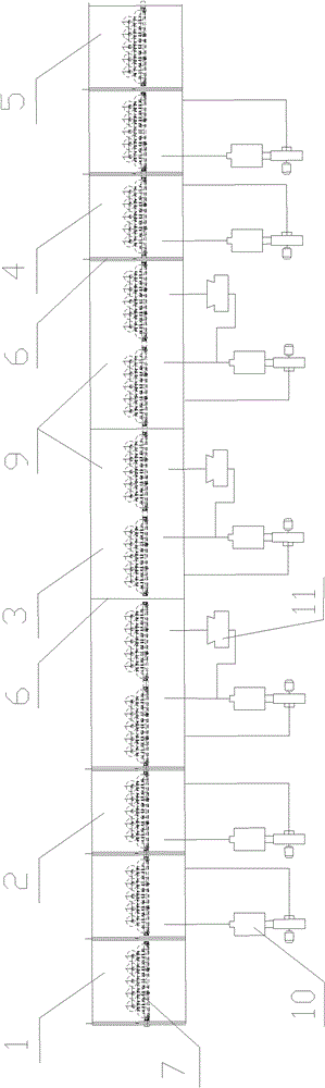
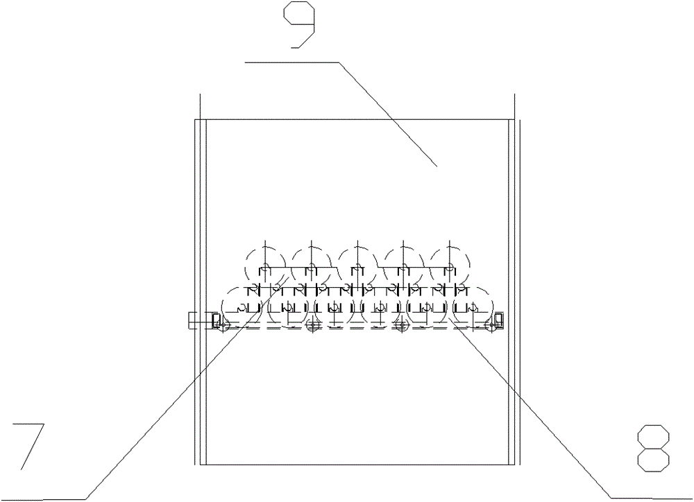
[0028] In the embodiment of the present invention, a moving material rack is set on the track running through the five intervals of the feeding area, the heating furnace area, the holding furnace area, the cooling furnace area and the discharging area, so that the aluminum coils on the material rack are driven to pass through in sequence. Through different temperature intervals, the continuous annealing process is completed. The following are specific examples.

...


PUM

PropertyMeasurementUnit
diameteraaaaaaaaaa
radiusaaaaaaaaaa

Abstract

The invention discloses an aluminum foil continuous annealing furnace which sequentially comprises a material inlet zone, a temperature rising furnace zone, a temperature maintaining furnace zone, a temperature lowering furnace zone and a material outlet zone, wherein the zones are sealed and separated through furnace doors, and a material rack moves on tracks penetrating through all the zones. Each of the temperature rising furnace zone, the temperature maintaining furnace zone and the temperature lowering furnace zone is divided into a plurality of chambers, wherein each chamber is connected with a hot-air blower, an opening of an air outlet pipeline of each hot-air blower is arranged under the horizontal plane where the bottom of the material rack in each chamber is located, an opening of an air sucking pipeline of each hot-air blower is arranged above the horizontal plane where the top of the material rack in each chamber is located, and the included angle of the plane where the air outlet pipeline is located and the plane where the air sucking pipeline is located is 90 degrees. According to the aluminum foil continuous annealing furnace, the material rack moves on the tracks penetrating through the material inlet zone, the temperature rising furnace zone, the temperature maintaining furnace zone, the temperature lowering furnace zone and the material outlet zone, an aluminum coil on the material rack can be driven to sequentially penetrate through the zones at different temperatures, and therefore a continuous annealing process is finished.

Description

technical field [0001] The invention relates to the technical field of changing the physical structure of nonferrous metals, in particular to a continuous annealing method for aluminum foil and a continuous annealing furnace. Background technique [0002] In the production process of aluminum foil, annealing is one of the most important processes in its heat treatment process. At present, the annealing equipment for aluminum foil mainly adopts the traditional box-type annealing furnace. The box-type annealing furnace has only one furnace space. After all the aluminum foils are stacked in the furnace, the temperature is slowly raised to the specified temperature, and the temperature is slowly lowered after a period of heat preservation; Roll it out, and wait until the furnace cavity is completely cooled before raising the temperature of the next furnace; the whole cycle takes 3-5 days. [0003] There are many problems with this box annealer and return method: [0004] 1. Be...

Claims


Application Information

Patent Timeline
Patent Type & Authority Patents(China)
IPC IPC(8): C21D9/56
Inventor 不公告发明人
Owner SNTO TECH GRP
Why Eureka
Try Eureka