
Automatic circulation plasma vapor phase deposition system

A technology of plasma gas and automatic circulation, applied in the field of ion vapor deposition system, to achieve the effect of stable valve core structure, wide application range and quality improvement

Active Publication Date: 2014-05-21
广东腾胜科技创新有限公司
View PDF6 Cites 0 Cited by
  • Summary
  • Abstract
  • Description
  • Claims
  • Application Information

AI Technical Summary

Problems solved by technology

However, the current plasma vapor deposition technology can only be applied to workpieces with small surface areas, and cannot be applied to workpieces with large surface areas such as glass for solar power generation.

Method used


Image

  • Automatic circulation plasma vapor phase deposition system
  • Automatic circulation plasma vapor phase deposition system
  • Automatic circulation plasma vapor phase deposition system

Examples


Embodiment 1

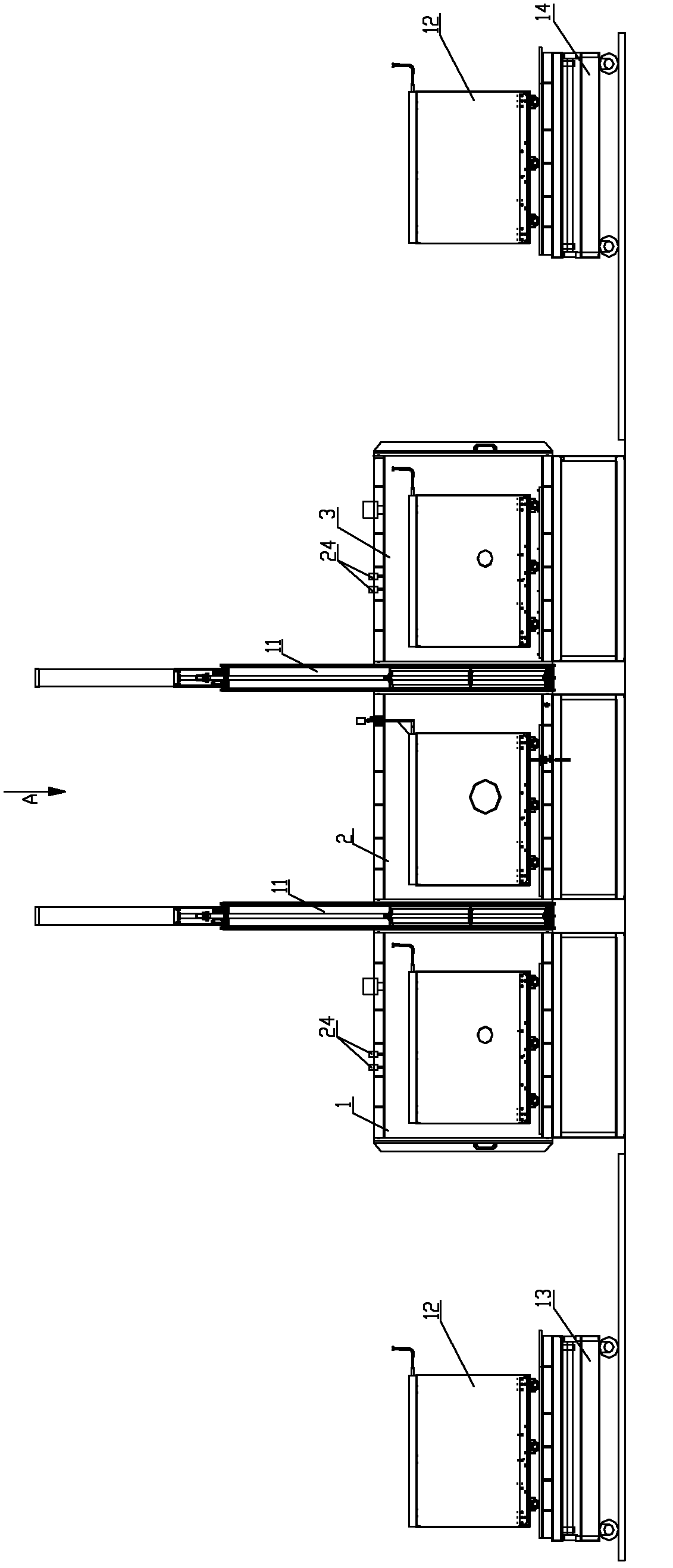
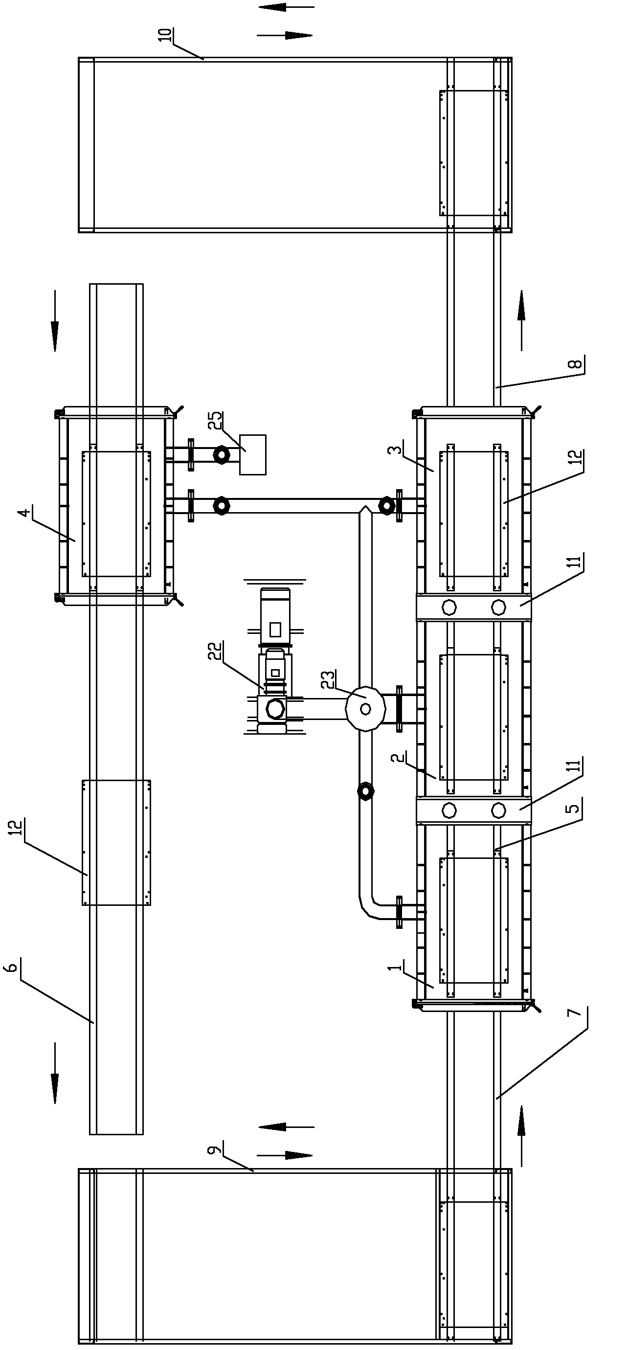
[0031] This embodiment is an automatic circulation plasma vapor deposition system, its structure is as follows figure 1 or figure 2 As shown, it includes a preheating chamber 1, a plasma vapor deposition chamber 2, a cooling chamber 3 and a cleaning chamber 4, the preheating chamber, the plasma vapor deposition chamber and the cooling chamber are sequentially connected by the first guide rail 5, and the cleaning chamber and the cooling chamber are arranged in parallel, The bottom of the cleaning room is provided with a second guide rail 6, and the two ends of the first guide rail are respectively provided with an entry guide rail 7 and an exit guide rail 8. 10 are connected and arranged perpendicular to each other, the first guide rail, the second guide rail, the first conveyor belt and the second conveyor belt form a rectangular structure; the preheating chamber, the plasma vapor deposition chamber, the cooling chamber and the cleaning chamber are respectively connected with...

Embodiment 2

[0041] This embodiment is an automatic circulation plasma vapor deposition system, its specific structure is as follows Figure 8 or Figure 9 As shown, compared with embodiment 1, its difference is that plasma vapor deposition chamber 2 has 6, and 6 plasma vapor deposition chambers are arranged in series between preheating chamber and cooling chamber, and each plasma vapor deposition chamber is connected with respectively The vacuum mechanism is connected, and a vacuum lock is arranged between two adjacent plasma vapor deposition chambers. For glass workpieces that require multi-layer deposition, multiple plasma vapor deposition chambers are provided, and each plasma vapor deposition chamber can be filled with different gases according to the process requirements, compared to alternately filling different gases in the same plasma vapor deposition chamber In this case, cross-contamination of different gases can be avoided.


PUM


Abstract

The invention discloses an automatic circulation plasma vapor phase deposition system which comprises a preheating chamber, at least one plasma vapor phase deposition chamber, a cooling chamber and a cleaning chamber, wherein the preheating chamber, the plasma vapor phase deposition chamber and the cooling chamber are sequentially connected by a first guide rail; the cleaning chamber is parallel to the cooling chamber, and a second guide rail is arranged at the bottom of the cleaning chamber; the two ends of the first guide rail are respectively connected with a first conveyer belt and a second conveyer belt by a chamber inlet guide rail and a chamber outlet guide rail; a rectangular structure is formed by the first guide rail, the second guide rail, the first conveyer belt and the second conveyer belt; the preheating chamber, the plasma vapor phase deposition chamber, the cooling chamber and the cleaning chamber are respectively and externally connected with a vacuumizing mechanism; and a vacuum lock is respectively arranged between each two adjacent vacuum chambers. The automatic circulation plasma vapor phase deposition system is provided aiming at the surface processing for a large-area workpiece, so the defect that the traditional technology is only applied to a workpiece with smaller surface area is overcome; and the automatic circulation plasma vapor phase deposition system is wide in application scope and convenient to use.

Description

technical field [0001] The invention relates to the technical field of flat substrate coating, in particular to an automatic circulation plasma vapor deposition system. Background technique [0002] Plasma Enhanced Chemical Vapor Deposition (PECVD) is the introduction of related gases when the power supply (including radio frequency power supply, DC power supply or AC power supply, etc.) equipment for electronic applications. Because the process has no environmental pollution, no chemical sewage discharge, low power consumption and high efficiency, it is gradually being applied. However, the current plasma vapor deposition technology can only be applied to workpieces with small surface areas, and cannot be applied to workpieces with large surface areas such as glass for solar power generation. Contents of the invention [0003] The purpose of the present invention is to overcome the deficiencies of the prior art and provide an automatic circulation plasma vapor depositio...

Claims


Application Information

Patent Timeline
Patent Type & Authority Patents(China)
IPC IPC(8): C23C16/44C23C16/54C03C17/00
Inventor 朱刚劲朱刚毅朱文廓
Owner 广东腾胜科技创新有限公司
Learn More