Wall brushing method for underground continuous wall

An underground continuous wall and wall brushing technology, applied in the field of construction engineering, can solve the problems of increasing the dead weight of the box, reducing the wall brushing efficiency, affecting the wall brushing effect, etc. Effect

Active Publication Date: 2012-07-11
SHANGHAI YUANFANG GROUNDWORK ENG
View PDF4 Cites 3 Cited by
  • Summary
  • Abstract
  • Description
  • Claims
  • Application Information

AI Technical Summary

Problems solved by technology

[0004] In the wall brushing process of the wall brusher, due to the use of a crane to brush the wall and the long arm of the crane, it is easy to cause the wall brusher to tilt, affecting the wall brushing effect, and it is necessary to rearrange the work stations, result

Method used


Image

  • Wall brushing method for underground continuous wall
  • Wall brushing method for underground continuous wall
  • Wall brushing method for underground continuous wall

Examples


Embodiment 1

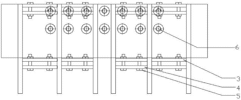
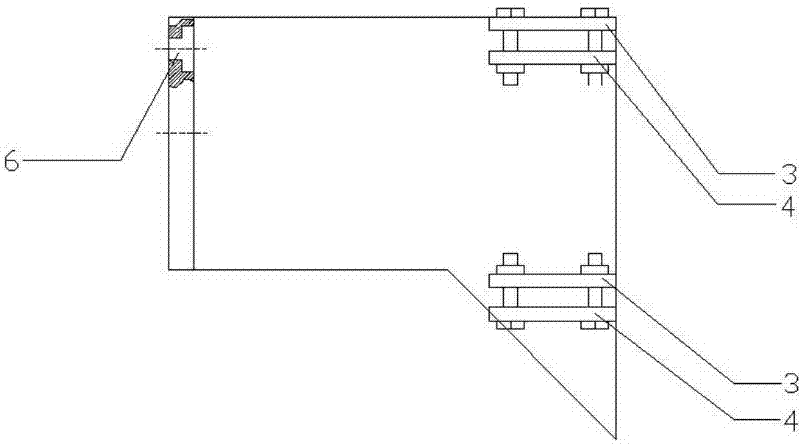
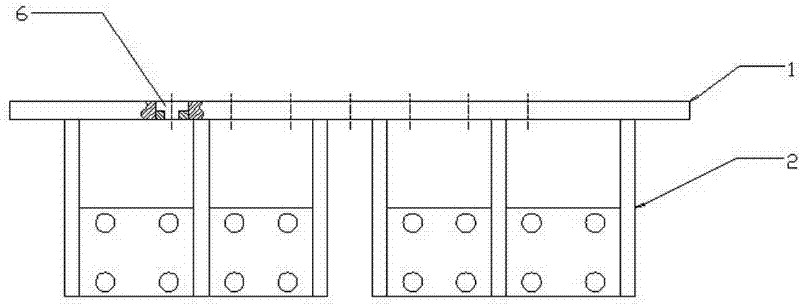
[0023] Embodiment one: if Figure 1~3 As shown, the connecting plate 1 is welded with six shovel plates 2 in the vertical direction, and the shovel plates 2 are in the shape of inverted bucket teeth. The shoveling plates 2 are distributed on the connecting plate 1 at certain intervals. At the gap between the shovel plates 2, that is, on the two adjacent sides of the shovel plate and the shovel plate, eight fixed plates 3 and eight movable plates 4 are welded, and the fixed plates 3 and the movable plates 4 are separated by a certain distance to form a Hollow cavity structure, eight sets of wire brushes are respectively fixed in the hollow cavity formed by the fixed plate 3 and the movable plate 4 through bolts 5 . There are also ten countersunk holes 6 on the connecting plate 1, and the countersunk holes 6 are matched with the holes on the scraper plate of the bucket frame body of the grooving machine. on board. according to figure 1 As shown, the present embodiment is di...

Embodiment 2

[0025] Embodiment two: if Figure 5-7 As shown, two semicircular fixed plates 3 are welded on the vertical direction of the connecting plate 1, and the other two plates are movable plates 4, a hollow cavity structure is formed between the two plates, and the wire brush is installed in the hollow through the bolt 5. inside the cavity. The connecting plate 1 is provided with a countersunk hole 6 for affixing with the slotting machine. According to Fig. 10, the installation of upper and lower two layers of wire brushes shown in Figure 11 all is finished by fixed plate 3, mobile plate 4 of same specification.

[0026] The second embodiment is actually implemented: this embodiment is used for joints with curved sections in the joints of underground diaphragm walls. The semicircular fixing plate used in this embodiment is used to brush the curved surface structure of the underground diaphragm wall joint. Since the wall surface of the curved surface structure is simple in processin...


PUM


Abstract

The invention relates to the field of constructional engineering, in particular to a wall brushing method for an underground continuous wall, which is characterized in that a connecting plate is fixedly arranged on a fixing bracket; the connecting plate is connected with and fixed on an outer vertical plane of a mud scraper of a ladder body of a grooving machine; the width of the connecting plate is not greater than that of the mud scraper; and then the grooving machine starts up, the ladder body of the grooving machine drives the fixing bracket to move upwards and downwards, so that a scrubbing surface of the underground continuous wall can be cleaned and brushed. The wall brushing method has the advantages as follows: bolted connection is adopted, so that convenient disassembly and assembly as well as simple operation can be achieved; a vertical fluctuation hoist of the grooving machine achieves a high speed and a high efficiency and saves a great deal of time in comparison with a crane; the ladder body of the grooving machine is heavier, so that a wall brushing device can utilize weight advantage to remove an obstacle when meeting with the obstacle; the verticality of the grooving machine is very good, so that the thoroughness for wall brushing is ensured, and the wall brushing effect is good; and the process is shortened, and a working face is saved.

Description

technical field [0001] The invention relates to the field of construction engineering, in particular to a wall-painting method for an underground continuous wall. Background technique [0002] The construction process of the underground diaphragm wall is carried out according to the unit groove section. When the adjacent unit groove sections are constructed sequentially, a connecting joint will be formed. Because there is wall mud in the groove section, the concrete surface of the connecting joint will be in the concrete during the construction process. A layer of mud skin forms on the surface. In order to ensure a good combination of the concrete poured in the later stage and the concrete poured in the previous stage at the joint position, avoid water leakage, and increase the integrity of the wall, after the completion of the subsequent groove section, the concrete surface of the previous groove section needs to be brushed. Treatment, remove the soil attached to the concr...

Claims


Application Information

Patent Timeline
IPC IPC(8): E02D29/16E02D29/02
Inventor 刘忠池姚海明李睿张中亮
Owner SHANGHAI YUANFANG GROUNDWORK ENG
Why Eureka
Try Eureka