Rectangular steel tube concrete column and steel beam all-bolt connecting joint

A technology of rectangular steel pipes and concrete columns, which is applied in the direction of construction and building construction, can solve the problems of large residual stress, brittle failure, and limitation of pipe column side length, so as to reduce stress concentration and brittleness, and prevent joint performance The effect of reducing and improving construction efficiency

Active Publication Date: 2012-07-11
TIANJIN UNIV
View PDF7 Cites 35 Cited by
  • Summary
  • Abstract
  • Description
  • Claims
  • Application Information

AI Technical Summary

Problems solved by technology

[0005] (1) Due to the difficulty of welding inside the joint, the pouring of concrete in the pipe is also affected by the internal diaphragm joint, which is often limited by the side length of the pipe string in application
In addition, there are beam flanges and inner partitions welded on both sides of the same position of the steel pipe column, and the steel is hot-processed twice, which tends to generate large residual stress, resulting in brittle failure near the weld
Although the structure of the joint itself is intended to make the plastic hinge appear at the beam end, the stress concentration at the weld affects the development of the plastic hinge
[0006] (2) Due to the structural characteristics of the node itself, the outer ring plate node has poor adaptability and flexibility
However, judging from the earthquake damage of the Northridge earthquake in the United States and the Hanshin earthquake in Japan, the damage of the bolted and welded joints of steel structures is very serious. The investigation of the damaged connections shows that the welds are prone to quality defects and many cracks Starts at the lower flange weld where the lower flange weld is interrupted and not easily ultrasonically inspected

Method used


Image

  • Rectangular steel tube concrete column and steel beam all-bolt connecting joint
  • Rectangular steel tube concrete column and steel beam all-bolt connecting joint
  • Rectangular steel tube concrete column and steel beam all-bolt connecting joint

Examples


Embodiment 1

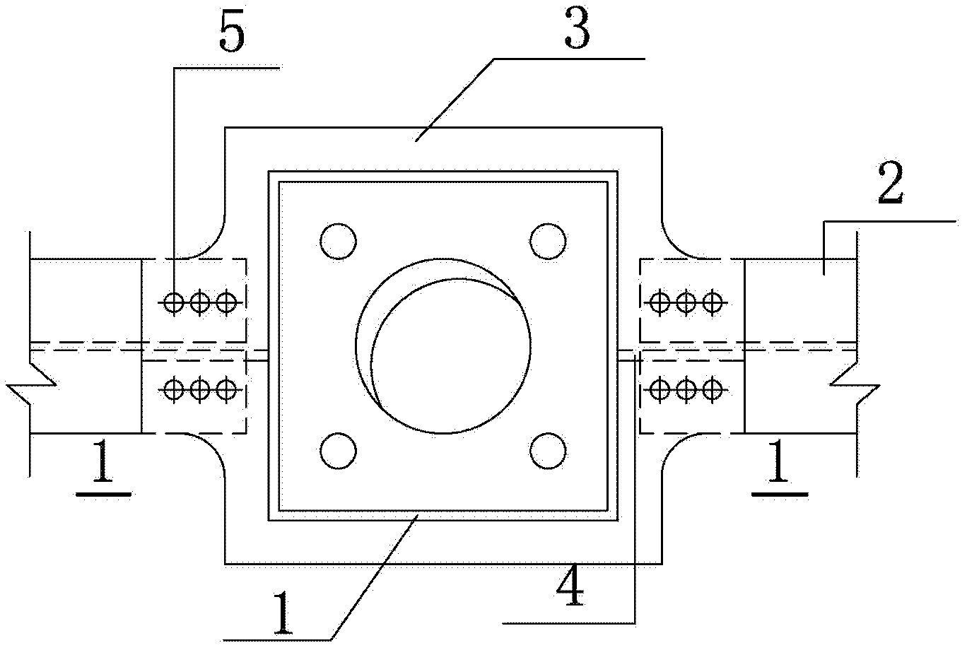
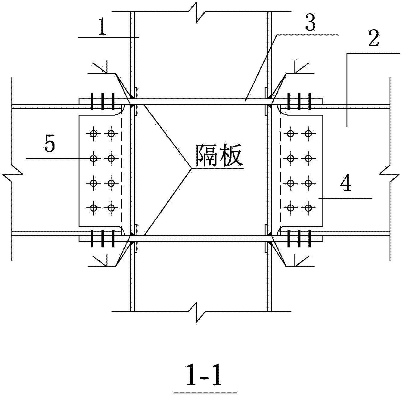
[0036] see figure 1 , figure 2 , rectangular steel pipe concrete column 1, steel beam 2, through partition 3, connection plate 4, high-strength bolt 5, wherein the through partition 3 runs through the wall of the rectangular steel pipe concrete column 1, and is welded with the surrounding wall of the steel pipe column Connection, the connecting plate 4 is welded to the side wall of the column and the upper and lower through partitions 3, the web of the steel beam 2 is bolted to the connecting plate 4, and the upper and lower flanges are bolted to the upper and lower through partitions 3 respectively. In this embodiment, the connecting plate is a connecting plate with long slots, and the upper and lower flanges of the steel beams are directly inserted into the long slots of the connecting plate.

[0037] In the above-mentioned beam-to-column connection node, the rectangular steel tube of the rectangular steel tube concrete column 1 is a welded steel plate, butt channel steel ...

Embodiment 2

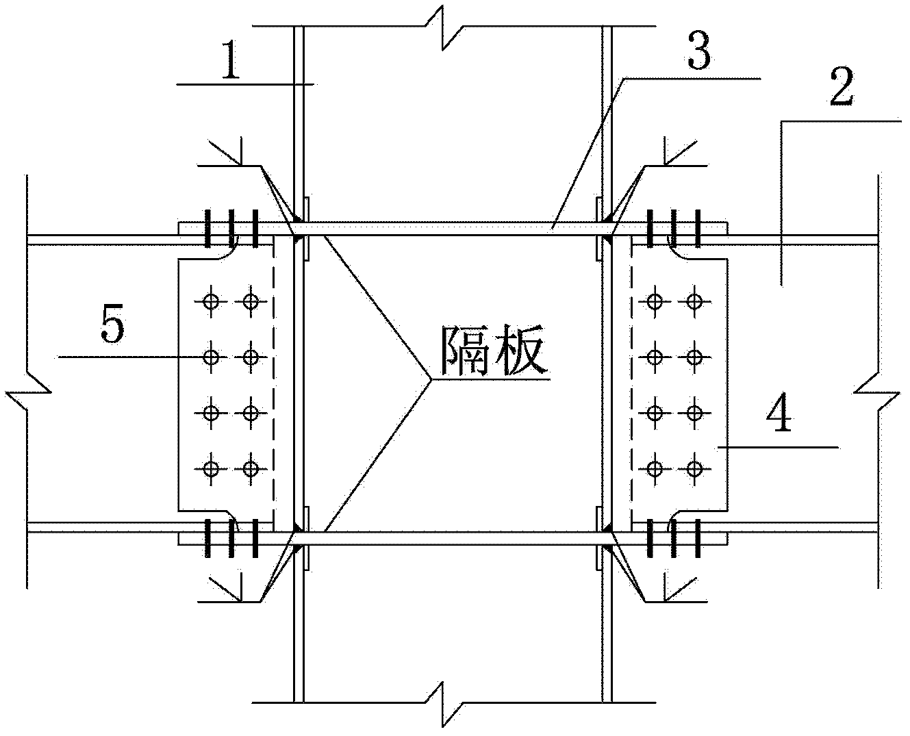
[0049] see image 3 The difference between embodiment 2 and embodiment 1 is that both the upper flange and the lower flange of the steel beam are grooved, the connecting plate has an arc-shaped cutout at the insertion opening of the steel beam, and the upper and lower flanges of the steel beam are directly inserted into the cutout of the connecting plate. When embodiment 2 is specifically used, the implementation process is:

[0050] 1) According to the size of the rectangular concrete-filled steel tube column 1, the through partition 3 is processed. On the side of the column not connected with the beam, the overhang length of the partition can be taken as 50 mm. A quarter arc with a radius of 60mm makes the partition transition to the same width as the steel beam;

[0051] 2) Bolt holes are reserved on the through partition 3, the diameter of which is slightly larger than the diameter of the high-strength bolt 5, and the number of reserved holes is calculated by the bending ...

Embodiment 3

[0058] see Figure 3-Figure 9 , the difference from Example 1 is that the steel beam in Example 3 is a steel beam with a long cut up and down on the web, and the connecting plate is a connecting plate without arc-shaped cutouts. The steel beam is located between the upper through partition according to the upper flange The upper and lower flanges are inserted under the lower through partition, and through the upper through partition and the upper side column wall, the ribs, the haunches between the lower through partition and the lower side column wall, or the upper through partition Add horizontal reinforcement plates on both sides of the slab and the lower through diaphragm to strengthen the node domain.

[0059] When this embodiment is used specifically, the implementation process is:

[0060] 1) According to the size of the rectangular concrete-filled steel tube column 1, the through partition 3 is processed. On the side of the column not connected with the beam, the over...


PUM


Abstract

The invention belongs to the technical field of building structure engineering, and relates to a rectangular steel tube concrete column and steel beam all-bolt connecting joint, which comprises a rectangular steel tube concrete column, a steel beam, an upper through partition board, a lower through partition board, a connecting plate and high-strength bolts. The upper through partition board and the lower through partition board penetrate through a wall of the rectangular steel tube concrete column, and are connected with the periphery of the wall of the rectangular steel tube concrete column via grooved weld joints, the connecting plate is welded with a side wall of the column, the upper through partition board and the lower through partition board, a web plate of the steel beam is connected with the connecting plate via the high-strength bolts, and an upper flange and a lower flange of the web plate of the steel beam are respectively connected with the upper through partition board and the lower through partition board via the high-strength bolts. The invention further discloses a method for manufacturing the rectangular steel tube concrete column and steel beam all-bolt connecting joint. The joint is fast in construction, simple in structure and fine in stress performance and seismic performance, and can meet requirements of outwards movement of plastic hinges.

Description

technical field [0001] The invention belongs to the technical field of building structure engineering, and in particular relates to a rectangular steel pipe concrete column-steel beam connection node. Background technique [0002] Concrete filled steel pipe structure is composed of steel pipes filled with concrete. The existence of steel pipes can prevent premature cracking of concrete, and the existence of concrete can prevent premature buckling of steel pipes. The joint work of the two can give full play to the high tensile performance of steel and the good compressive performance of concrete. Therefore, it has many advantages such as high bearing capacity, good plasticity and toughness, good seismic performance, significant economic benefits and environmental protection in construction. [0003] The rectangular concrete-filled steel tube structure has the advantages of high flexural rigidity and convenient joint connection. The frame structure system formed by rectangula...

Claims


Application Information

Patent Timeline
Patent Type & Authority Applications(China)
IPC IPC(8): E04B1/58
Inventor 陈志华秦颖王小盾
Owner TIANJIN UNIV
Why Eureka
Try Eureka