
Engine-driven generator

An engine-driven, generator technology, applied in the direction of engine control, engine frame, machine/engine, etc., can solve the problems of reducing the size, weight and cost of the whole machine, fuel tank occupancy, occupancy, etc., to increase aesthetics, reduce The effect of size

Inactive Publication Date: 2012-07-11
CHONGQING RATO POWER
View PDF9 Cites 4 Cited by
  • Summary
  • Abstract
  • Description
  • Claims
  • Application Information

AI Technical Summary

Problems solved by technology

In a traditional open-frame generator, the fuel tank occupies the entire upper space of the frame, and the control panel (i.e., the control unit) is arranged on the left, right, or front and rear sides of the frame, as shown in the accompanying drawings of the patent with publication number CN1423079A; In order to increase the commerciality of the product, the two ends of the two upper sides of the frame are designed to be inclined, but the space below the inclined section is basically wasted, as shown in the accompanying drawing of the patent with the publication number CN300703282
Regardless of whether the control unit is arranged on the left, right, or front and rear sides of the rack, because the control panel needs to occupy a certain space, the size of the whole rack will increase in length or width or height; and at the same time, because the present invention considers when designing Increasing the frequency conversion function of the generator will increase the length of the frame to a certain extent. If the layout of the control unit is not considered in the design, it will be unfavorable to reduce the size, weight and cost of the whole machine

Method used


Image

  • Engine-driven generator
  • Engine-driven generator
  • Engine-driven generator

Examples


Embodiment Construction

[0026] Next, when describing the embodiment of the present invention with reference to the accompanying drawings, the direction in which the handle 7 pulls the engine-driven generator 10 is taken as the front.

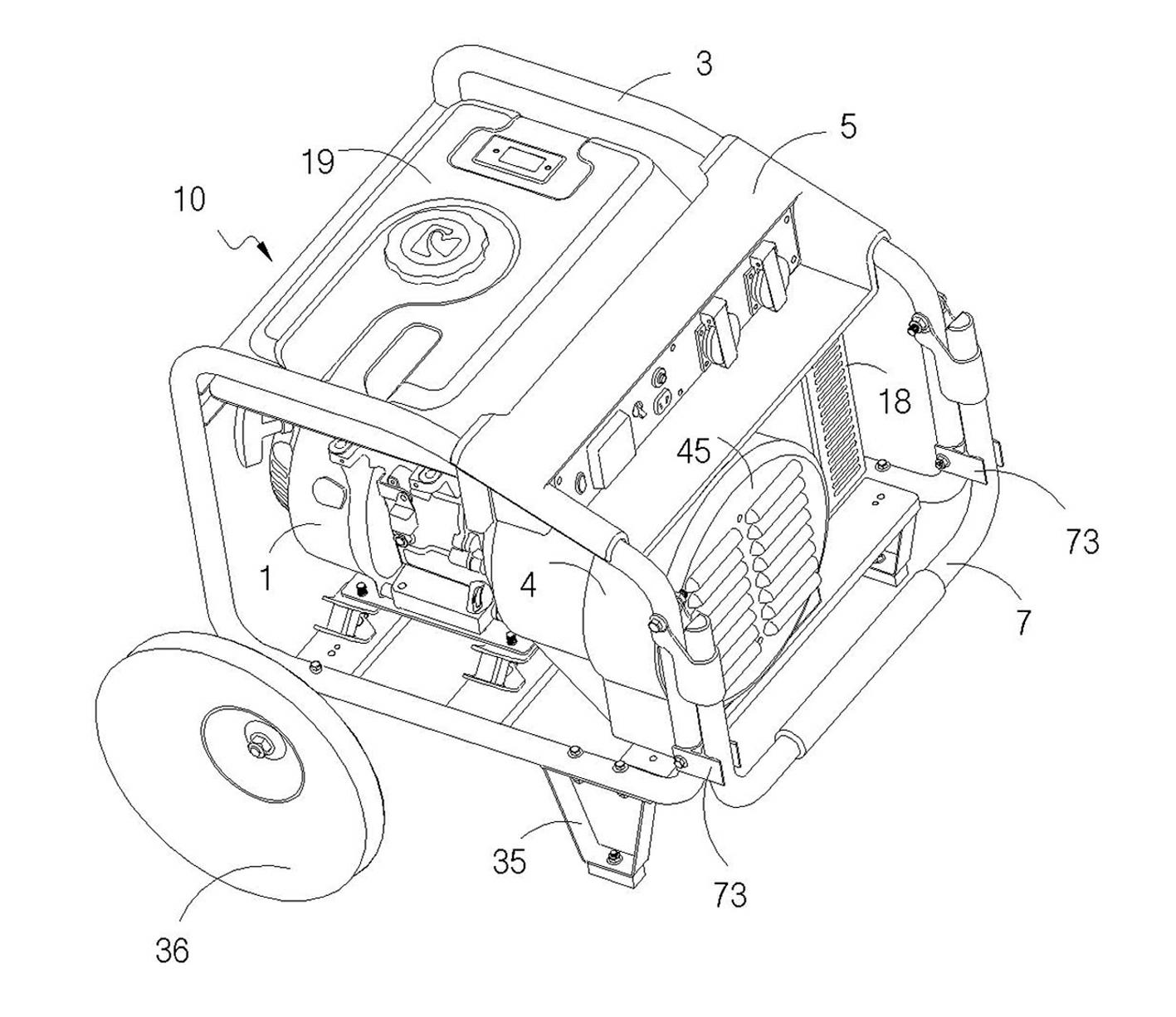
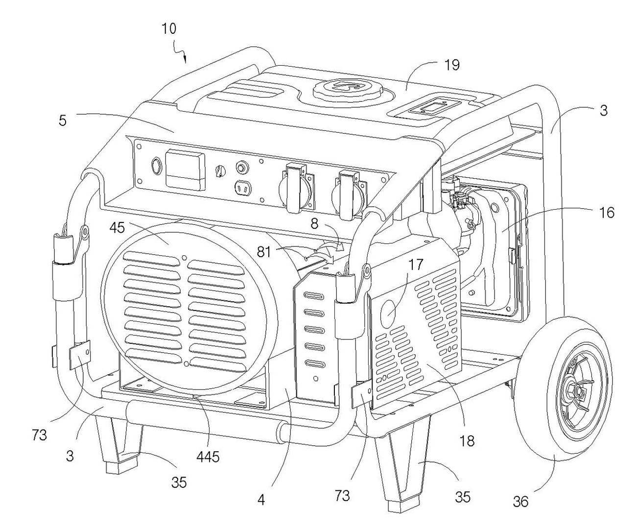
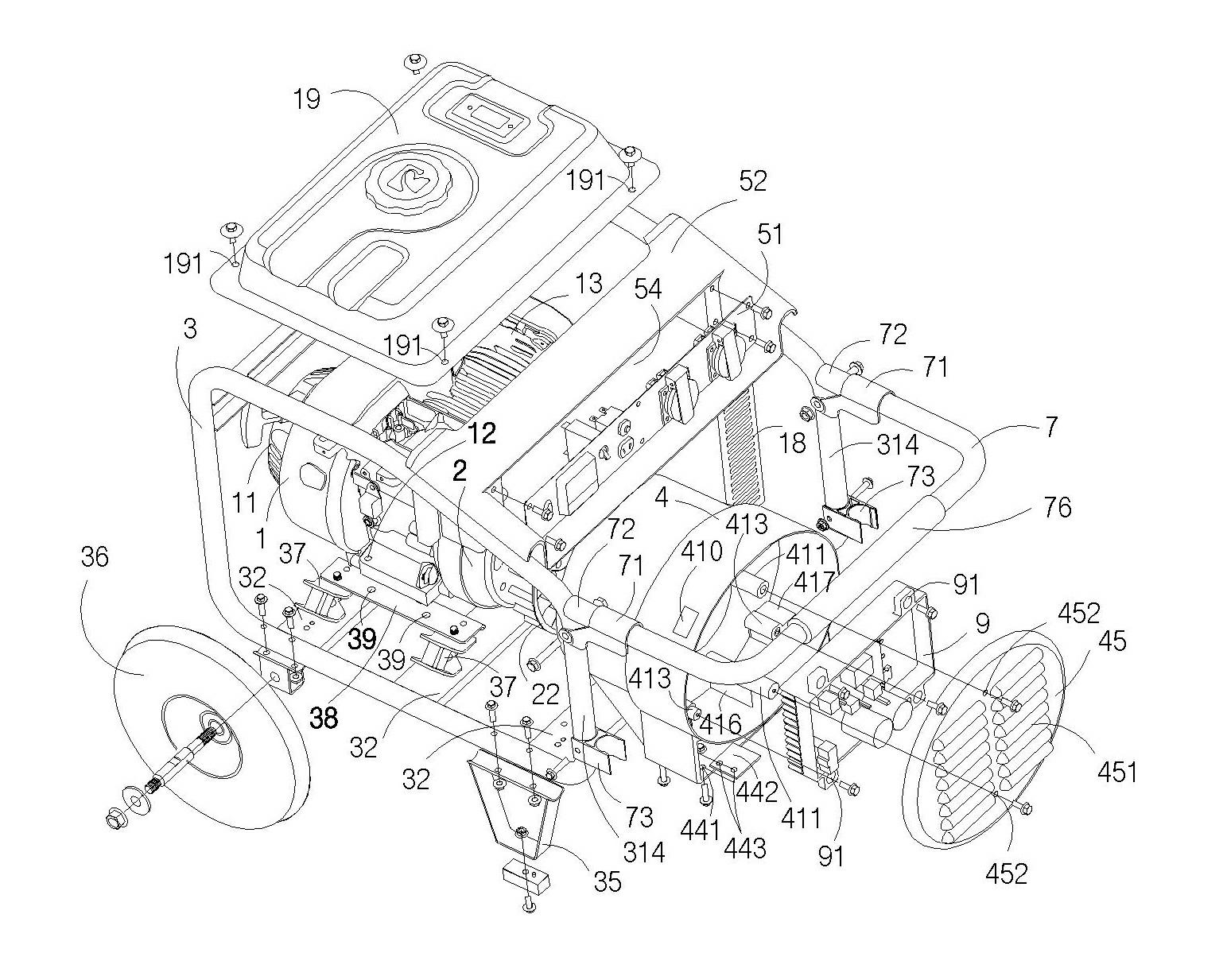
[0027] Such as figure 1 , image 3 As shown, the engine-driven generator 10 has: a frame 3 forming a supporting frame of the engine-driven generator 10; an engine 1 and a generator 2 coaxially driven by the engine 1, both elastically supported on the frame 3 The generator 2 is connected with a motor fan 22; the fuel tank 19 provides fuel for the engine 1; the electrical unit 9 controls the current output, and in an embodiment, the electrical unit 9 refers to the inverter (of course, except Inverter, also can comprise other electrical components); Control unit 5, it is installed in the space between two inclined sections 312b, 312b above frame 3 (referring to Figure 4 ), used to control the operation of the engine-driven generator 10; the cooling shell 4, used to gui...


PUM


Abstract

The invention provides an engine-driven generator, wherein free space of the generator in the prior art is reasonably utilized to arrange a control unit, thus commodity of a product is guaranteed while dimension, weight and cost can be beneficially reduced. The engine-driven generator is in the structure that an engine and a generator driven by the engine are supported on a rack, the rack is in the structure that a left side frame and a right side frame are made by bending a steel pipe and are of a square shape, one end of the upper side part of each side frame is inclined downward, the lower side parts of the side frames are connected into a whole by virtue of a transverse construction member, the upper parts of the side frames are connected into a whole by virtue of a front support construction member and a rear support construction member, wherein the front support construction member is arranged below a position close to the starting point of the inclined section of the upper side part of each side frame; meanwhile, the transverse construction member elastically supports an assembling body of the engine and the generator, the front support construction member and the rear support construction member are respectively provided with a fuel tank which is covered above the engine in a dismountable manner, and a control unit which is used for controlling the engine-driven generator to operate and is covered above the generator is arranged between the inclined sections in the dismountable manner.

Description

technical field [0001] The invention relates to a frame type generator driven by an engine, in particular to the arrangement of a frame, an oil tank and a control unit. Background technique [0002] Engine-driven generators are basically composed of engines, generators, racks, fuel tanks, control panels, etc. According to different racks, engine-driven generators are divided into open-frame generators with open frames around the frame and closed-frame generators around the frame. The silent generator, the open frame generator is generally used in low-end places with low noise requirements, while the silent generator is used in mid-to-high-end places with relatively high noise requirements. The generator involved in the present invention is an open-frame generator aimed at the low-end market and a generator-driven generator that takes into account the frequency conversion requirements. In a traditional open-frame generator, the fuel tank occupies the entire upper space of th...

Claims


Application Information

Patent Timeline
IPC IPC(8): F02B63/04F02D29/06F16M3/00
Inventor 周华闵绍明华祥顺
Owner CHONGQING RATO POWER
Learn More