Electro hydraulic valve

A hydraulic valve and electric technology, applied in the field of hydraulic valves, to achieve the effects of fast response, strong oil resistance and large torque

Active Publication Date: 2012-07-11
SANY HEAVY IND CO LTD (CN)
View PDF6 Cites 9 Cited by
  • Summary
  • Abstract
  • Description
  • Claims
  • Application Information

AI Technical Summary

Problems solved by technology

[0004] In order to solve the problem of small output force of the hydraulic valve in the prior art, limited spool stroke, slow response speed, poor anti-pollution ability, limited single-stage control ability; bulky volume and poor reliability when the flow rate is high; vibration and noise are easily generated inside; Low control precision, poor linearity and other problems or at least one of them, the present invention provides an electrohydraulic valve, which can effectively overcome the technical problems in the above-mentioned prior art

Method used


Image

  • Electro hydraulic valve
  • Electro hydraulic valve
  • Electro hydraulic valve

Examples


Embodiment Construction

[0042] In order to enable those skilled in the art to better understand the technical solutions of the present invention, the present invention will be further described in detail below in conjunction with the accompanying drawings and specific embodiments.

[0043] In the following description, many specific details are set forth in order to fully understand the present invention, but the present invention can also be implemented in other ways different from those described here, therefore, the present invention is not limited to the specific embodiments disclosed below limit.

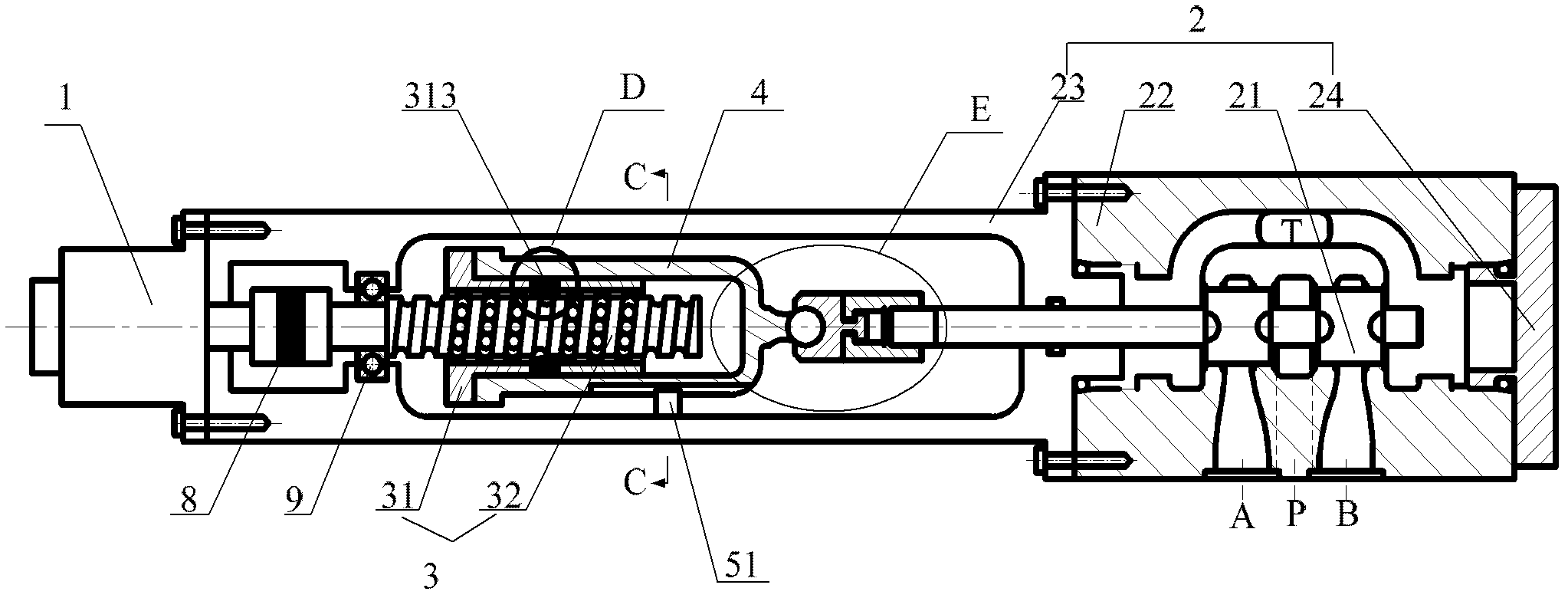
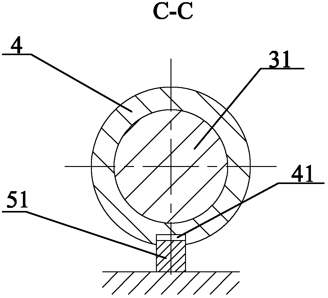
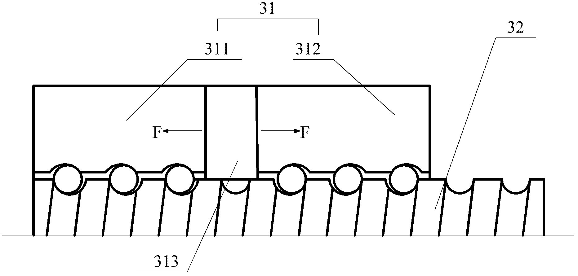
[0044] Such as Figure 1 to Figure 4 Shown is an embodiment of the electrohydraulic valve according to the present invention. in, figure 1 It is a structural schematic diagram of this embodiment of the electrohydraulic valve; figure 2 for figure 1 C-C sectional view in ; image 3 for figure 1 Enlarged view of part D in ; Figure 4 for figure 1 Enlarged view of part E in .

[0045] refer to ...


PUM


Abstract

The invention provides an electro hydraulic valve. The electro hydraulic valve comprises a servo motor and a hydraulic valve which are connected with each other; and the servo motor can drive a valve plug of the hydraulic valve to move. The electro hydraulic valve is high in response speed, eliminates the problem of vibration noise caused by hydraulic impact, is high in control accuracy and linearity and overcomes the defects in the prior art that an electromagnet is used as an electro-mechanical convertor.

Description

technical field [0001] The invention relates to the technical field of hydraulic valves, in particular to an electrohydraulic valve driven by a servo motor. Background technique [0002] At present, the electro-mechanical converters of hydraulic valves are generally ordinary electromagnets, proportional electromagnets, etc. The hydraulic valve first converts the electrical signal into a force signal through the above-mentioned electromagnet, and then converts the force signal into a hydraulic valve by cooperating with the spring. The mechanical displacement signal of the spool controls the displacement of the hydraulic valve spool so that the hydraulic valve operates at the set outlet pressure / outlet flow. [0003] The above-mentioned hydraulic valves in the prior art have at least the following problems due to the limitations of the inherent characteristics of the electromagnet: the output force of the electromagnet is small, and the output stroke is limited, resulting in a...

Claims


Application Information

Patent Timeline
Patent Type & Authority Applications(China)
IPC IPC(8): F15B13/02
Inventor 易小刚李东白子龙张作良
Owner SANY HEAVY IND CO LTD (CN)
Why Eureka
Try Eureka