Crank and connecting rod transmission mechanism and main transmission system of punch

A technology of main transmission system and transmission mechanism, applied in the field of main transmission system, can solve the problems of poor performance stability, inability to adjust, fast friction plate loss, etc., and achieve the effect of increasing flexibility, improving efficiency, and expanding processing.

Inactive Publication Date: 2014-12-24
JINAN CASTING FORGING MACHINERY INST
View PDF8 Cites 0 Cited by
  • Summary
  • Abstract
  • Description
  • Claims
  • Application Information

AI Technical Summary

Problems solved by technology

Although the structure is relatively simple and the manufacturing cost is low, the disadvantages are that the friction plate wears quickly, is highly polluting, and has poor performance stability. Its eccentricity is unique and cannot be changed. Can not be adjusted at the time, waste of resources, low efficiency, and need frequent adjustment and maintenance, noisy

Method used


Image

  • Crank and connecting rod transmission mechanism and main transmission system of punch
  • Crank and connecting rod transmission mechanism and main transmission system of punch
  • Crank and connecting rod transmission mechanism and main transmission system of punch

Examples


Embodiment 1

[0026] Embodiment 1: crank-link transmission mechanism with variable eccentricity.

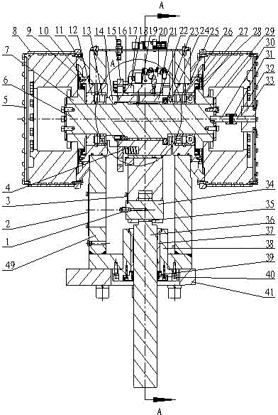
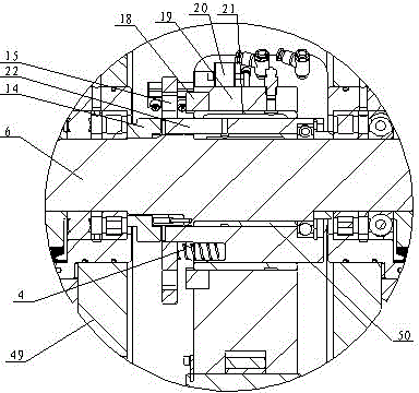
[0027] A crank-link transmission mechanism with variable eccentricity, the transmission mechanism is divided into two different forms, one is a mechanism form with double eccentricity conversion, and the other is a mechanism form with triple eccentricity conversion. Two kinds of transmission mechanism all are to comprise crankshaft 6, connecting rod 19 and eccentric distance variable device, and eccentric distance variable device is made up of fixed tooth nest 14, tooth nest 18, crankshaft eccentric sleeve 22, conversion sleeve 15 etc., fixed The tooth socket 14 is connected to the crankshaft 6 through a spline; the tooth socket 18 is fixed on the connecting rod 19 by screws; slide.

[0028] The crankshaft offset sleeve 22 is set on the crankshaft 6, and the first lubricating copper sleeve 50 is arranged between them to play a role in lubrication. The connecting rod 19 is sleeved on the crank...

Embodiment 2

[0035] Embodiment 2: A new CNC turret punch press main drive system powered by CNC single / double servo motors.

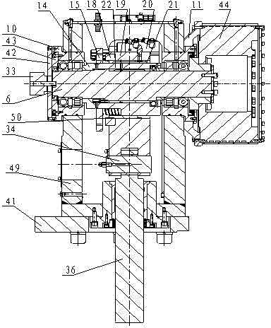
[0036] A punch servo main transmission system of a crank-link transmission mechanism with variable eccentricity, including a servo motor connected in sequence, the crank-link transmission mechanism described in Embodiment 1, and the crank-connect rod transmission mechanism described in Embodiment 1. The guide sleeve 37, the slide block 36 and the punch are characterized in that the single / double servo motor 44 is directly connected with the crank-link transmission mechanism described in Embodiment 1, and directly drives the movement of the crank-link transmission mechanism described in Embodiment 1, Drive the work of guide bush 37, slide block 36 and punch that link to each other with the crank-link transmission mechanism, finish stamping action.

[0037] Such as figure 1 , image 3 As shown, the main transmission system of the new CNC turret punch press is power...

Embodiment 3

[0038] Embodiment 3: The main transmission system of a new CNC turret punch press powered by a CNC servo motor and a reducer.

[0039] Such as Figure 4 As shown, the same crank-link transmission mechanism as in embodiment 1 and the servo motor control system similar to embodiment 2 are used, and the structure of the reducer is added. Connect the crank-link mechanism described in Embodiment 1, the speed reducer 47 and the servo motor II 48 in sequence. The output torque can be improved by the deceleration of the speed reducer 47, and the torque output ratio is multiplied by the motor output by the reduction ratio; the speed reduction of the speed reducer 47 reduces the inertia of the load, and the reduction of the inertia is the square of the reduction ratio.


PUM


Abstract

A crank and connecting rod transmission mechanism comprises a crankshaft and a connecting rod, and is characterized in that a fixed jaw sleeve and a crankshaft eccentric sleeve are sleeved on the crankshaft in parallel, the fixed jaw sleeve is fixedly connected with the crankshaft, a first copper lubricating bush is arranged between the crankshaft eccentric sleeve and the crankshaft, a connecting rod and a jaw sleeve are sleeved at the outer edge of the crankshaft eccentric sleeve through a second copper lubricating bush, the jaw sleeve is fixedly connected with the connecting rod, a switching sleeve with jaw units is sleeved on the crankshaft eccentric sleeve and capable of sliding thereon, and a switching sleeve driving device is arranged on the connecting rod. The crank and connecting rod transmission mechanism is mainly used for a main transmission system of a punch, has the advantages of energy economization, noise reduction, capability of increasing efficiency and processing optimization, and can be applied to numerical-control punch equipment widely.

Description

technical field [0001] The invention relates to a crank connecting rod transmission mechanism with variable eccentricity and a main transmission system of a novel numerically controlled turret punch press powered by a servo motor. It belongs to the technical field of mechanical design and manufacture. Background technique [0002] The CNC turret punch press is the key equipment for sheet metal stamping. As the main transmission part of the stamping power, the traditional mechanical design of the crank linkage mechanism is as follows: Figure 9 As shown, the crank-link mechanism composed of crankshaft 55 , connecting rod 53 , pin 52 , slide block 51 and the like and flywheel 56 are installed on the fuselage 54 . Clutch and brake 58 are respectively connected with the right shaft end of crankshaft 55 , and are controlled by the main control valve 57 in action. During work, the main motor drives the flywheel 56 to rotate through the belt, and transmits the power to the cranksh...

Claims


Application Information

Patent Timeline
Patent Type & Authority Patents(China)
IPC IPC(8): F16H21/18B21D22/00
Inventor 李兵张建设
Owner JINAN CASTING FORGING MACHINERY INST
Why Eureka
Try Eureka