Installation and control method of hydraulic control butterfly valve control device based on SMART 3

A control device, hydraulic control butterfly valve technology, applied in the direction of valve device, valve operation/release device, valve details, etc., can solve the heat dissipation of electronic components in the controller box, poor anti-vibration performance, and the valve controller cannot be quickly and effectively Problems affecting the safe operation of the steam turbine heating butterfly valve, etc., to reduce the frequency of power cut/supply, prevent the wrong interval and misoperation risk, and maintain the effect of social image

Pending Publication Date: 2021-12-14
HUANENG GANSU XIGU THERMAL POWER CO LTD
View PDF0 Cites 0 Cited by
  • Summary
  • Abstract
  • Description
  • Claims
  • Application Information

AI Technical Summary

Problems solved by technology

[0002] The deterioration trend of the valve controller equipment in the prior art is obvious. During operation, the failure of the heating butterfly valve is often out of control. After the valve controller fails, it cannot be quickly and effectively dealt with. Affecting the Safe Operation of Steam Turbine Heating Butterfly Valve

Method used


Image

  • Installation and control method of hydraulic control butterfly valve control device based on SMART 3
  • Installation and control method of hydraulic control butterfly valve control device based on SMART 3
  • Installation and control method of hydraulic control butterfly valve control device based on SMART 3

Examples


Embodiment 1

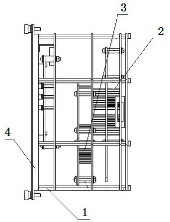
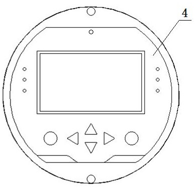
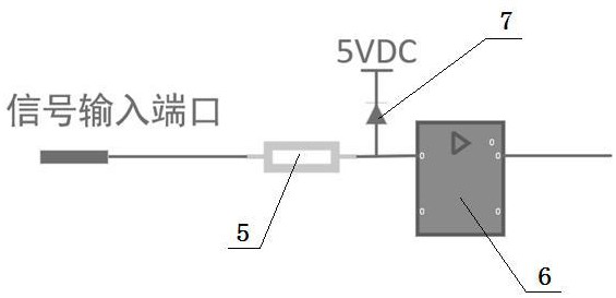
[0027] A hydraulically controlled butterfly valve control device based on SMART 3, which consists of: a support column connection device 1, an EMC device, and is characterized in that: the support column connection device is a frame structure, and terminals are plug-in installed in the lower frame B3, the middle position of the frame is plugged with terminal A2, the end surface of the support column connection device is installed with the control panel 4 and connected by bolts, the terminal A and the terminal B are respectively connected to the electrical system Connection, the signal input port of the EMC device is connected to the diode clamp circuit 5 of the current limiting resistor, and a dual power switch 7 is installed between the diode clamp circuit of the current limiting resistor and the signal amplification circuit 6 .

Embodiment 2

[0029] An installation and control method of the SMART 3-based hydraulic control butterfly valve control device described in Embodiment 1-2, the method is:

[0030] (1) First, install a dual power switch and power indicator on the control device to reduce the frequency of switching / sending power from the power cabinet entering the electronic equipment room, and prevent wrong intervals and misoperations;

[0031] (2) The PDI board, CPU board, and AIO board for the power supply of the valve actuator controller are installed in a stacked frame to enhance the anti-vibration performance of the controller. The terminal A and terminal B connection of the type connection increases the installation space in the control cabinet, increases the heat dissipation space for heat dissipation of electronic components and signal transmission;

[0032] (3) Set the control system to adapt to the ambient temperature at 85°C, the display screen uses an OLED screen with a working temperature of -40~...


PUM


Abstract

The invention discloses an installation and control method of a hydraulic control butterfly valve control device based on SMART 3. A valve controller in the prior art often causes failure and out-of-control of a heat supply butterfly valve, the failure cannot be quickly and effectively treated, and safe operation of the heat supply butterfly valve of a steam turbine is affected. The device comprises a supporting column connecting device (1) and an EMC device, wherein the supporting column connecting device is of a frame structure, a terminal B (3) is installed in a frame below the supporting column connecting device in a plug-in mode, a terminal A (2) is installed in the middle of the frame in a plug-in mode, and a control panel (4) is installed on the end face of the supporting column connecting device and connected with the supporting column connecting device through a bolt; the terminal A and the terminal B are respectively and electrically connected with an electrical system, a signal input port of the EMC device is connected with a diode clamping circuit (5) of the current-limiting resistor, and a dual-power change-over switch (7) is installed between the diode clamping circuit of the current-limiting resistor and a signal amplification loop (6). The hydraulic control butterfly valve control device based on the SMART 3 is provided.

Description

technical field [0001] The invention relates to the technical field of steam turbine heating butterfly valves, in particular to an installation and control method of a SMART 3-based hydraulic control butterfly valve control device. Background technique [0002] The deterioration trend of the valve controller equipment in the prior art is obvious. During operation, the failure of the heating butterfly valve is often out of control. After the valve controller fails, it cannot be quickly and effectively dealt with. It affects the safe operation of the steam turbine heating butterfly valve. Contents of the invention [0003] The purpose of the present invention is to provide an installation and control method of a hydraulically controlled butterfly valve control device based on SMART 3, through the transformation of the board installation structure of the valve hydraulic actuator control system PDI card, CPU card, AIO card, etc., the board circuit optimization Technical measu...

Claims


Application Information

Patent Timeline
Patent Type & Authority Applications(China)
IPC IPC(8): F16K31/02
CPCF16K31/02
Inventor 孙晓赵宇袁斌彬成红兵芦晓丽
Owner HUANENG GANSU XIGU THERMAL POWER CO LTD
Why Eureka
Try Eureka