Solar roof ventilating device and method of zero energy consumption unattended power plant

A technology for power plant workshops and ventilation devices, applied in ventilation systems, space heating and ventilation, heating and ventilation control systems, etc., can solve problems such as increased personnel discomfort, low indoor temperature, aging or broken light-transmitting panels, etc. Achieve the effect of obvious energy saving, environmental protection and economic advantages, change the system composition, and reduce the complexity of construction

Inactive Publication Date: 2012-07-11
HENNAN ELECTRIC POWER SURVEY & DESIGN INST +2
View PDF4 Cites 14 Cited by
  • Summary
  • Abstract
  • Description
  • Claims
  • Application Information

AI Technical Summary

Problems solved by technology

However, this method has the following major disadvantages or reliability problems
[0005] (1) In summer, when the solar radiation is large during the day, the luminous flux in the factory building may be too high to affect human vision, and the radiation heat gain entering the room is also the largest, which will greatly increase the cooling load of indoor ventilation. In principle, it needs to be further improved. The amount of ventilation is used to compensate, which increases the initial investment and operating costs of the ventilation system
[0006] (2) After sunset in winter, especially on sunny days, the surface of the building envelope and the surface of equipment can form a radiation heat effect with the outdoor sky, which further lowers the indoor temperature and increases the discomfort of personnel. will increase

Method used


Image

  • Solar roof ventilating device and method of zero energy consumption unattended power plant
  • Solar roof ventilating device and method of zero energy consumption unattended power plant

Examples


Embodiment Construction

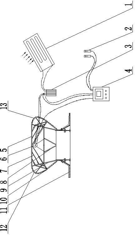
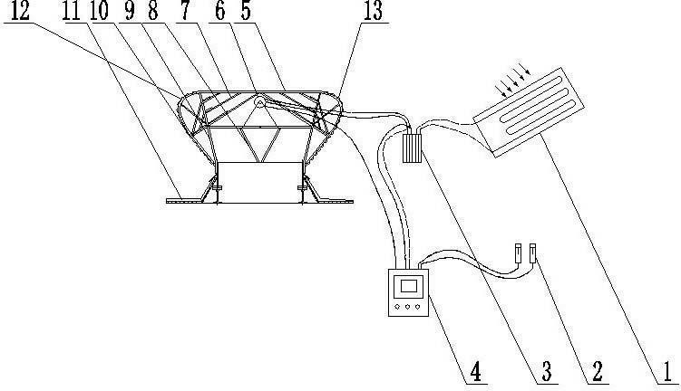
[0025] Such as figure 1 As shown, the present invention is composed of a ventilator 5 and a solar photovoltaic drive device; at least one set of valve plates 8 and a motor 6 connected to the valve plate are arranged in the ventilator 5, and the motor 6 is driven by the solar photovoltaic drive device. The above-mentioned solar photovoltaic driving device includes a solar photovoltaic panel 1, and the solar photovoltaic panel 1 and the storage battery 3 form an independent series circuit connection, and the storage battery 3 and the load part form a series power supply connection. When there are multiple sets of storage batteries, the storage batteries form a parallel connection. The motor 6 and the intelligent controller 4 of the load part form a parallel circuit connection, and the whole circuit realizes island operation without connection with the public power grid. The input end of the intelligent controller 4 is connected to the temperature sensor 2 , and the output end th...


PUM


Abstract

The invention provides a solar roof ventilating device of a zero energy consumption unattended power plant. The solar roof ventilating device consists of a ventilator and a solar photovoltaic driving device. At least one group of valve plates and a motor connected with the valve plates are arranged in the ventilator; and the motor is driven by the solar photovoltaic driving device. The solar photovoltaic driving device comprises a solar photovoltaic panel, the solar photovoltaic panel is connected in series with a storage battery, and the storage battery is connected with an intelligent controller and a motor, wherein the input end of the intelligent controller is connected with a temperature sensor, and the output end of the intelligent controller is connected with the motor. According to the solar roof ventilating device disclosed by the invention, a solar photovoltaic generation technology is applied to the roof ventilator for the first time, so that a novel energy source, namely solar energy, is used for supplying electric power to all electric components of the roof ventilator, and zero manual energy consumption is realized by avoiding access to a public power grid. The solar photovoltaic driving device is integrally designed. A user only needs to replace a former manual power distribution system by the solar photovoltaic driving device, and then the solar roof ventilating device can control drive operation by using the novel energy source to the former roof ventilator; and the construction complexity is reduced.

Description

technical field [0001] The invention belongs to the technical field of roof ventilators and new energy sources, and in particular relates to a zero-energy unattended solar roof ventilator for power plants. Background technique [0002] In order to eliminate harmful dust and gas pollutants generated during the production process, eliminate waste heat and humidity, and meet the hygiene requirements of the personnel in the work area, the power plant workshop usually needs to adopt comprehensive ventilation, in which the roof is made of indoor heat and external heat pressure and outdoor wind pressure. The ventilator is a main form of controlling the overall ventilation operation, which saves the power consumption of the fan and its operating cost compared with the way of controlling the ventilation volume by relying on a large fan. However, the motor used for the control valve plate of the existing roof ventilator still needs to be equipped with external power transmission and d...

Claims


Application Information

Patent Timeline
IPC IPC(8): F24F7/02F24F11/02H02N6/00
Inventor 张茂勇严迪春
Owner HENNAN ELECTRIC POWER SURVEY & DESIGN INST
Why Eureka
Try Eureka