Longitudinal flow shell-and-tube heat exchanger

A flow tube and heat exchanger technology, applied in the field of longitudinal flow shell-and-tube heat exchangers, can solve the problems of heat transfer enhancement fluid and tube bundle surface shear force, increase of friction fluid dissipation work, etc., to achieve enhanced axial Degree of mixing and turbulence, low power consumption, effect of increased turbulence

Inactive Publication Date: 2012-07-11
HUAZHONG UNIV OF SCI & TECH
View PDF3 Cites 9 Cited by
  • Summary
  • Abstract
  • Description
  • Claims
  • Application Information

AI Technical Summary

Problems solved by technology

[0004] The invention provides a shell-and-tube heat exchanger with longitudinal flow, which solves the problem that the heat transfer of the existing shell-and-tube heat exchanger is strengthened while the shearing force and friction force on the surface of the fluid and the tube bundle are greatly increased, as well as the dissipation work of the fluid is greatly increased.

Method used


Image

  • Longitudinal flow shell-and-tube heat exchanger
  • Longitudinal flow shell-and-tube heat exchanger
  • Longitudinal flow shell-and-tube heat exchanger

Examples


Embodiment 1

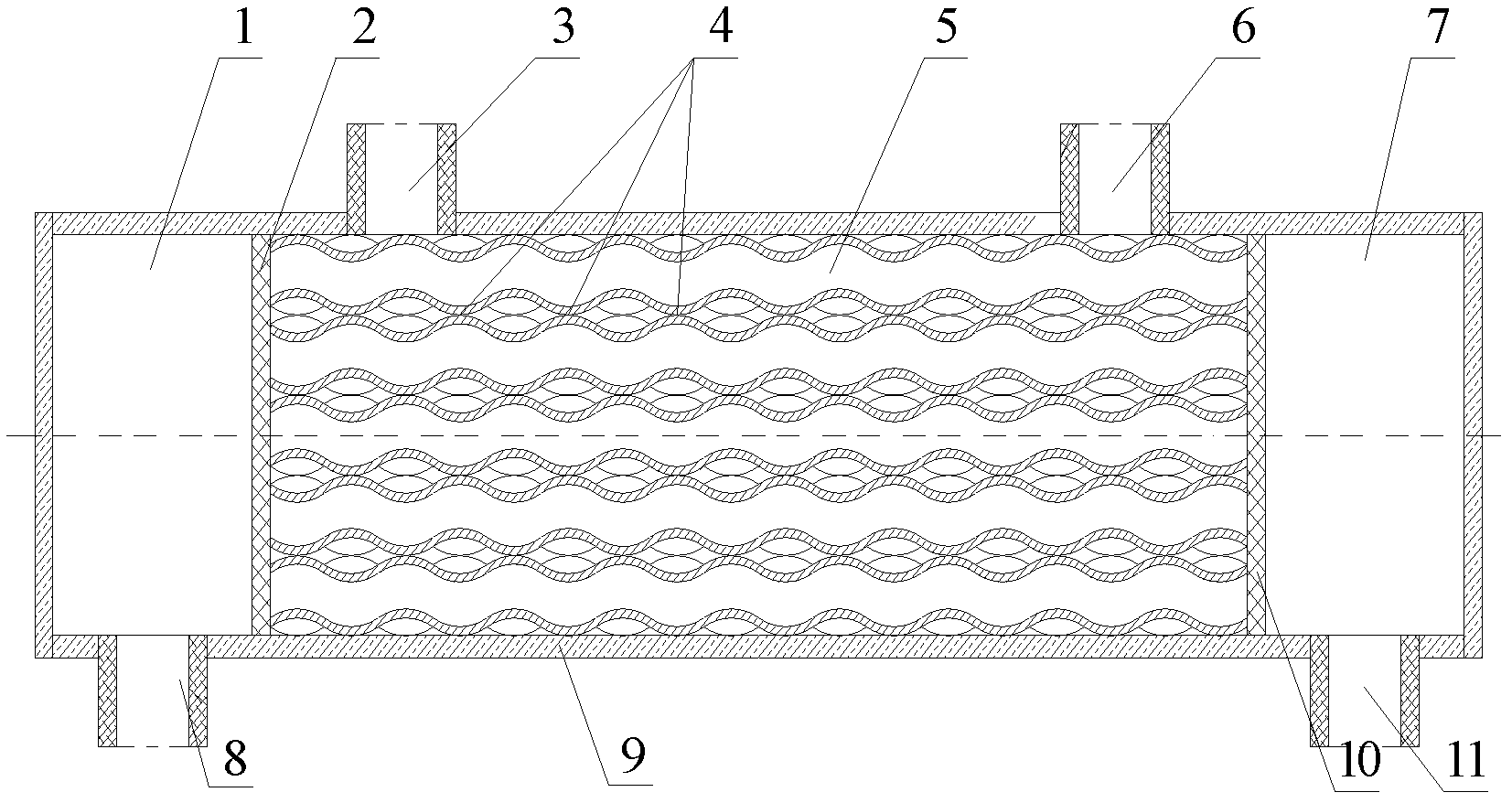
[0026] Such as figure 1 As shown, the first embodiment of the present invention includes a housing 9, a left tube plate 2, a right tube plate 10, a left head 1 and a right head 7, and the side wall of the housing has a shell side inlet 3 and a shell side outlet 6. The shell 9 is provided with a left tube plate 2 and a right tube plate 10 respectively. The 21 heat transfer tubes 5 pass through the left and right tube plates and are fixed by the left and right tube plates. The head 7 is closed, and the left and right heads are respectively provided with a tube side inlet 11 and a tube side outlet 8, and the tube side inlet and outlet and the shell side inlet and outlet are arranged in reverse.

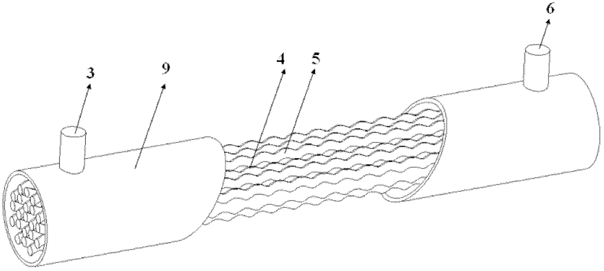
[0027] Such as figure 2 As shown in the first embodiment, the left and right tube plates and the shell parts of the left and right heads are removed. The figure only shows the shell side inlet 3, the shell side outlet 6, the heat transfer tube 5 and the shell 9; the inner diameter of the sh...

Embodiment 2

[0034] The second embodiment, the structure is the same as the first embodiment, the 12 heat transfer tubes pass through the left and right tube plates and are fixed by the left and right tube plates, the inner diameter of the shell is 9.5mm, and the wall thickness of the shell is 1mm;

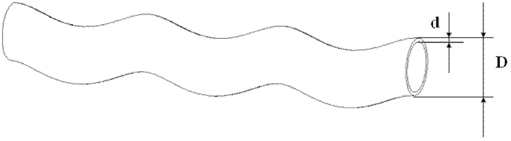
[0035] Any cross-sectional shape of the spiral heat transfer tube is a circle with equal radius, the inner diameter D of the spiral heat transfer tube is 1.4mm, and the wall thickness d is 0.2mm; the central axis of the spiral heat transfer tube is a cylindrical helix. The following conditions are met in the Cartesian coordinate system:

[0036] x=a×cosθ,

[0037] y=a×sinθ,

[0038] z=S×θ / 2π,

[0039] Among them, x, y, z are the coordinates of each point on the cylindrical spiral line in the Cartesian coordinate system of the x, y, and z axis central axis, z is 100mm, the variable θ is the angle, the spiral radius a is 0.25mm, The distance S is 4mm.

Embodiment 3

[0040] The third embodiment, the structure is the same as the first embodiment, 480 heat transfer tubes pass through the left and right tube plates and are fixed by the left and right tube plates, the inner diameter of the shell is 4180mm, and the wall thickness of the shell is 100mm;

[0041] Any cross-sectional shape of the spiral heat transfer tube is a circle with equal radius, the inner diameter D of the spiral heat transfer tube is 140mm, and the wall thickness d is 20mm; the central axis of the spiral heat transfer tube is a cylindrical helix. The following conditions are met in the coordinate system:

[0042] x=a×cosθ,

[0043] y=a×sinθ,

[0044] z=S×θ / 2π,

[0045] Among them, x, y, z are the coordinates of each point on the cylindrical spiral line in the Cartesian coordinate system of the x, y, and z axis central axis, z is 20000mm, the variable θ is the angle, the spiral radius a is 25mm, and the pitch S is 400mm.

[0046] Figure 5 ~ Figure 10 For the results of numerical si...


PUM


Abstract

The invention discloses a longitudinal flow shell-and-tube heat exchanger, which belongs to shell-and-tube heat exchangers and solves the problem that the fluid dissipative work is increased during heat transfer enhancement of the conventional shell-and-tube heat exchanger. The longitudinal flow shell-and-tube heat exchanger comprises a shell, left and right tube plates and left and right seal heads, wherein the side wall of the shell is provided with a shell pass inlet and a shell pass outlet; the left and right tube plates are arranged in the shell respectively; a plurality of heat transfer tubes are fixed through the left and right tube plates; two ends of the shell are sealed by the left and right seal heads; the left and right seal heads are provided with a tube pass inlet and a tube pass outlet respectively; the heat transfer tubes are spiral heat transfer tubes; and in a direction vertical to a shell pass fluid flowing direction, the heat transfer tubes which contact the inner wall of the shell are supported through contact points of adjacent heat transfer tubes and contact points on the inner wall of the shell, and the other heat transfer tubes support and fix one another through the contact points of the adjacent heat transfer tubes. The longitudinal flow shell-and-tube heat exchanger is compact in structure, small in volume and large in heat exchange area, and saves the investment cost; and the contact points among tube bundles of the heat transfer tubes increase the turbulence intensity of the fluid during shell pass flow, the fluid is uniformly mixed, and the shell pass pressure drop is greatly reduced, so that the comprehensive heat exchange performance of the longitudinal flow shell-and-tube heat exchanger is improved.

Description

Technical field [0001] The invention belongs to a shell-and-tube heat exchanger, and specifically relates to a longitudinal-flow shell-and-tube heat exchanger. Background technique [0002] Shell and tube heat exchangers are widely used in petroleum, chemical, metallurgy, electric power and other industries due to their simple structure and low cost, accounting for about 70% of the total heat exchangers. The shell-side baffle structure of the shell-and-tube heat exchanger plays a role of overall flow turbulence on the one hand, and supports and fixes the tube bundle on the other hand. According to the flow direction of the shell-side fluid, shell-and-tube heat exchangers can be divided into three types: 1. Lateral flow, such as a traditional bow-shaped baffle, so that the shell-side fluid can wash the heat transfer tube vertically to form a lateral flow; 2. Longitudinal flow, such as a baffle rod heat exchanger, makes the shell side fluid flow parallel to the longitudinal direct...

Claims


Application Information

Patent Timeline
Patent Type & Authority Applications(China)
IPC IPC(8): F28D7/02
Inventor 刘伟杨杰杨金国刘志春马良王英双杨昆范爱武黄晓明
Owner HUAZHONG UNIV OF SCI & TECH
Why Eureka
Try Eureka