
Self-adaptive sum-difference angle measurement method for plane phased array

An adaptive, planar phase technology, applied in measuring devices, radio wave measurement systems, radio wave reflection/re-radiation, etc., can solve the problems of target signal attenuation, inability to estimate target angle, increase target angle error, etc., to achieve The effects of enhancing the target signal, improving the performance of anti-mainlobe interference, and improving the accuracy of angle measurement

Inactive Publication Date: 2012-07-11
XIDIAN UNIV
View PDF1 Cites 27 Cited by
  • Summary
  • Abstract
  • Description
  • Claims
  • Application Information

AI Technical Summary

Problems solved by technology

[0005] (1) Due to the small discrimination between the interference and the signal space, the target signal is severely attenuated while the interference is suppressed, the signal-to-interference-noise ratio is improved slightly, and the effect of suppressing the main lobe interference is not obvious, so it cannot be further used for target angle estimation;
[0006] (2) Due to the cracking of the main lobe of the pattern, the pattern of the sum-difference beam is greatly distorted, and the linear relationship is no longer satisfied in the main lobe. Larger, resulting in a larger calculated deflection angle, resulting in an increase in the error of the measured target angle, and even seriously deviating from the real target angle

Method used


Image

  • Self-adaptive sum-difference angle measurement method for plane phased array
  • Self-adaptive sum-difference angle measurement method for plane phased array
  • Self-adaptive sum-difference angle measurement method for plane phased array

Examples


Embodiment Construction

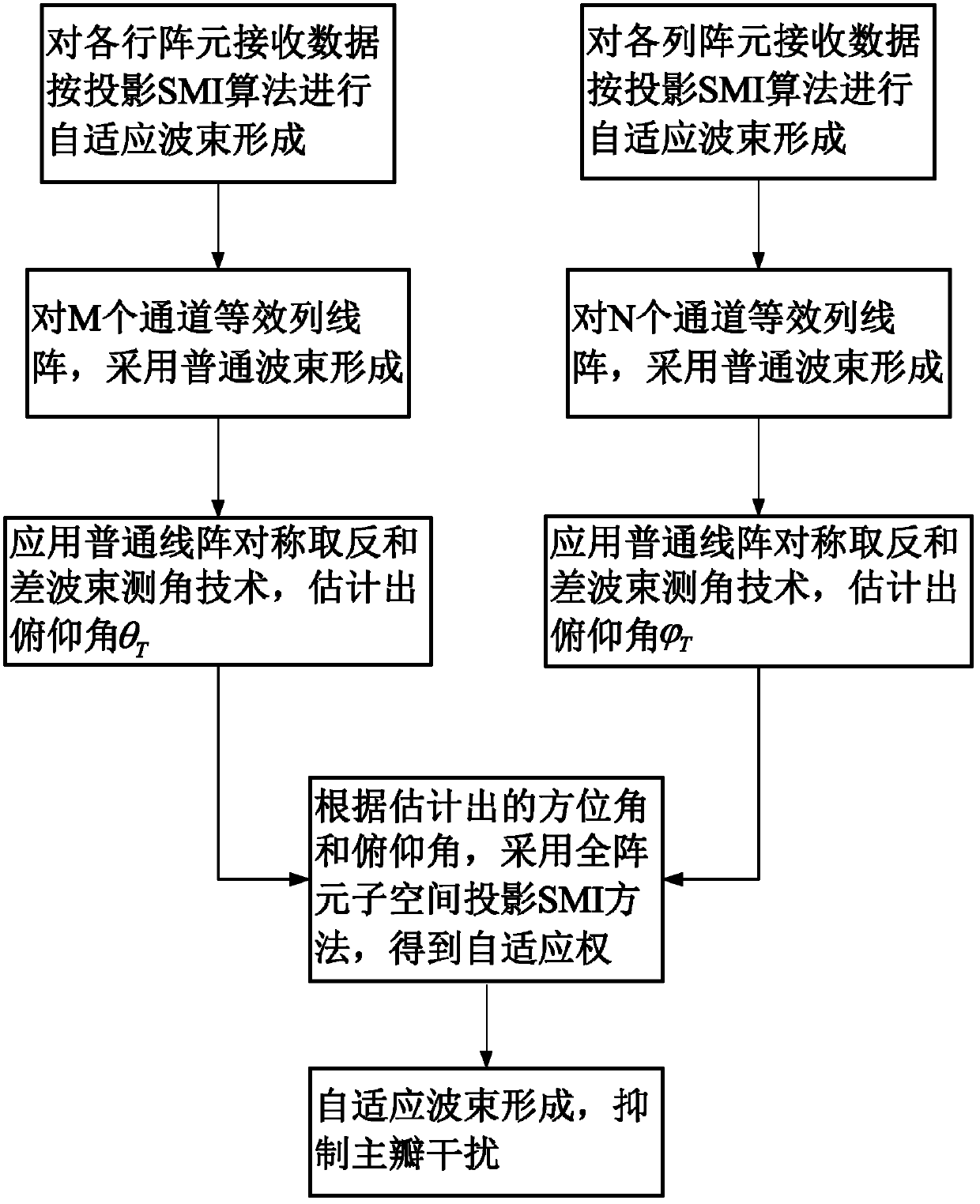
[0024] refer to figure 1 , realize the steps of the present invention as follows:

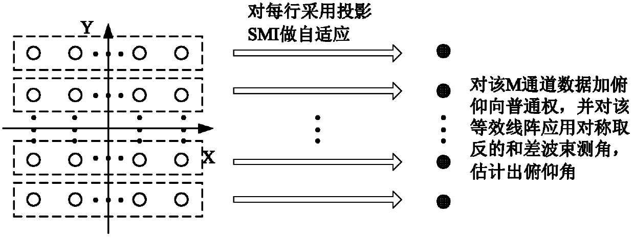
[0025] Step 1 performs adaptive beamforming on the received data of each row of array elements, and its output forms an equivalent linear array in the Y direction.

[0026] refer to figure 2 , this step is specifically implemented as follows:

[0027] (1a) Denote the received data of each row of array elements in the planar array as x r_k (t), where k=1, 2, ... M, first fix k=1, means to process the received data of the first row, and then use the sampling values ​​of 128 times at different times to estimate the received data x of the row array element r_k The covariance matrix of (t): in,(·) H Indicates matrix conjugate transpose, K=128, x r_k (t i ), i=1, 2, ..., K represents the sampling value of each row of array elements at different times;

[0028] (1b) Covariance matrix of row array elements Carry out eigendecomposition, decompose it into the multiplication and accumulation f...


PUM


Abstract

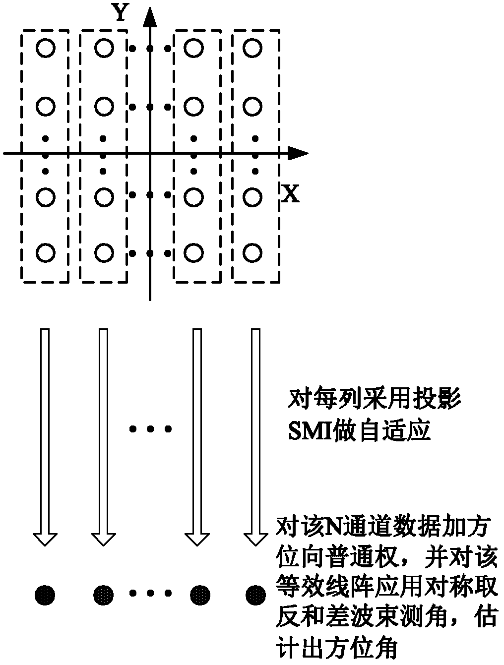
The invention discloses a self-adaptive sum-difference angle measurement method for a plane phased array, which mainly solves the problem of the prior art that the target angle cannot be estimated accurately while the main lobe interference is restrained. The realization process is that the self-adaptive beam formation is performed for received data of array elements of all the lines, an equivalent linear array of the output of the beam formation is formed in the Y-direction, and the sum-difference beam formation in symmetry inversion is adopted to estimate the target pitching angle theta T; the self-adaptive beam formation is performed for the received data of the array elements of all the rows, an equivalent linear array of the output of the beam formation is formed in the X-direction, and the sum-difference beam formation in symmetry inversion is adopted to estimate the target azimuth angle; and the self-adaptive beam formation for all the received data of all the array elements can be performed through adopting the subspace projection SMI algorithm and based on the pitching angle theta T and the azimuth angle, so as to obtain an output signal for restraining the main lobe interference. The method provided by the invention has the advantages of excellent performance of restraining the main lobe interference, as well as accuracy in sum-difference beam angle measurement, and can be used for estimating the angle of the target and tracking the target on the premise that the main lobe interference exists.

Description

technical field [0001] The invention belongs to the field of array signal processing, and relates to a sum-difference angle measuring method of a plane array, which can be used to realize phased array self-adaptive anti-jamming output and accurate estimation of the direction of arrival of a target when there is main lobe interference, and to track the target. Background technique [0002] "Sum difference angle measurement" is a method that uses the ratio of the difference beam to the sum beam to obtain the angle detection curve, and estimates the angle of the target according to the slope of the angle detection curve. It is widely used in radar, measurement and control, navigation, communication, electronic reconnaissance In the phased array system, to measure the direction of arrival of the radiation source. Due to the increasingly complex electromagnetic environment and the increasing hostile interference, anti-interference has become one of the necessary requirements for ...

Claims


Application Information

Patent Timeline
IPC IPC(8): G01S13/58G01S7/36
Inventor 曾操孔永飞陶海红廖桂生周志伟何学辉谈维林
Owner XIDIAN UNIV
Learn More