Method for calibrating near-field effect of spherical composite array in radio frequency simulation system

A composite array and radio frequency simulation technology, which is applied in the transmission system, transmitter monitoring, transmission monitoring, etc., can solve the problems of high cost and inability to meet the correction accuracy of near-field effect of the spherical composite array, and achieve the effect of overcoming errors and accurate control

Active Publication Date: 2016-12-07
EAST CHINA NORMAL UNIV +1
View PDF7 Cites 15 Cited by
  • Summary
  • Abstract
  • Description
  • Claims
  • Application Information

AI Technical Summary

Problems solved by technology

Due to the high cost of the electromagnetic wave anechoic chamber and simulation test system, usually the hardware-in-the-loop simulation system cannot meet the "far-field conditions" required for the test, and the system to be tested generally works in the "near-field radiation" area of ​​the triplet. , it is necessary to effectively correct the near-field effect of the simulation system; as the application development requires, the test requires that the RF hardware-in-the-loop simulation system can provide a more complex electromagnetic environment, and realize the target signal of multiple frequency bands on the same transmitting antenna array. The spherical compound array has also been proposed, and the correction method for the near-field effect of a single array cannot meet the correction accuracy of the near-field effect of the spherical compound array

Method used


Image

  • Method for calibrating near-field effect of spherical composite array in radio frequency simulation system
  • Method for calibrating near-field effect of spherical composite array in radio frequency simulation system
  • Method for calibrating near-field effect of spherical composite array in radio frequency simulation system

Examples


Embodiment 1

[0044] Microwave / millimeter wave triplet near-field effect calibration in spherical composite array, including the following:

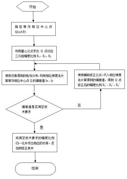
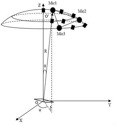
[0045]Firstly, the simulation model is established, and any group of adjacent microwave / millimeter wave antennas in the spherical composite array is selected to form a triplet and its input power is given as an initial value. The microwave antennas and millimeter wave antennas in other positions are not given input power. The receiving antenna axis points to the triplet antenna Mic1.

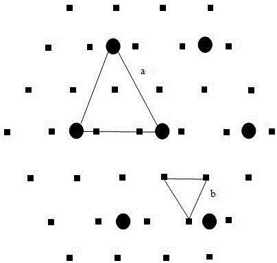
[0046] Set the equivalent phase center to the mid-perpendicular line of the plane connecting the two antennas where the triplet is located, the mid-perpendicular line is divided into ten equal parts, and the nine interval points are the positions of the equivalent phase center. According to the center of gravity formula, the initial value of the input power that should be given to each unit of the triplet when the target signal comes from different positions on the mid-...


PUM


Abstract

This invention discloses a method for calibrating near-field effect of a spherical composite array in a radio frequency simulation system, and relates to the technical field of instrument calibration. The spherical composite array is composed of micro wave and millimeter wave antenna arrays so as to generate electromagnetic wave signals of micro wave and millimeter wave frequency bands. The calibrating method comprises the steps of precisely calculating an electric field distribution near the position of a receiving antenna (normally located at a radiation near field of a transmitting triple antenna) by a full-wave algorithm and a high-frequency algorithm when a given subarray (triple) antenna in the composite array is transmitted in a surrounding environment of same-frequency and different-frequency antenna element; based on phase distribution of an electric field, determining an equivalent phase center of a triple radiation field by a phase gradient algorithm, and calculating a deviation between the equivalent phase center and an equivalent phase center estimated value acquired based on a gravity equation; and calibrating the input power ratio of each unit of the triple according to the deviation value. The method can be used for making a calibrating table, so as to quickly calibrate the near-field effect of the composite array in real time during engineering.

Description

technical field [0001] The invention belongs to the technical field of instrument equipment calibration, and relates to a calibration method for the near-field effect of a spherical composite array in a radio frequency simulation system. Background technique [0002] The radio frequency hardware-in-the-loop simulation system plays an irreplaceable role in the performance evaluation of the missile guidance system, system parameter debugging and verification, flight test result prediction and fault recurrence, etc. It can not only effectively shorten the missile development cycle, but also greatly save scientific research funds. Hardware-in-the-loop simulation can solve the problems that some parts in mathematical simulation are not easy to model and the cost of physical simulation is high, and the structure is difficult to modify in radar system simulation. The semi-physical radio frequency simulation system generally includes the following six parts: electromagnetic wave ane...

Claims


Application Information

Patent Timeline
Patent Type & Authority Applications(China)
IPC IPC(8): H04B17/12H04B17/391
CPCH04B17/12H04B17/3912
Inventor 程波朱守正付璐卞家骏于庭祥朱伟华王立权庞旭东张宇柳超杰
Owner EAST CHINA NORMAL UNIV
Why Eureka
Try Eureka