Method for reducing transmission time delay of distributed redundancy control system

A control system and transmission delay technology, applied in general control systems, control/regulation systems, instruments, etc., can solve problems such as large delay, untimely signal transmission, and uncertainty of data sending and receiving time, so as to ensure real-time, The effect of reducing the delay

Inactive Publication Date: 2012-07-11
FLIGHT AUTOMATIC CONTROL RES INST
View PDF4 Cites 6 Cited by
  • Summary
  • Abstract
  • Description
  • Claims
  • Application Information

AI Technical Summary

Problems solved by technology

[0004] Since each function board in the distributed redundancy flight control system operates asynchronously, the traditional task trigger method is used for data exchange, and the time of data transmission and reception cannot be determined, resulting in untimely signal transmission and large delay, which affects the real-time performance of the entire system. Not conducive to signal transmission and control calculations of distributed control systems

Method used


Image

  • Method for reducing transmission time delay of distributed redundancy control system
  • Method for reducing transmission time delay of distributed redundancy control system
  • Method for reducing transmission time delay of distributed redundancy control system

Examples


Embodiment Construction

[0014] The present invention will be described in further detail below.

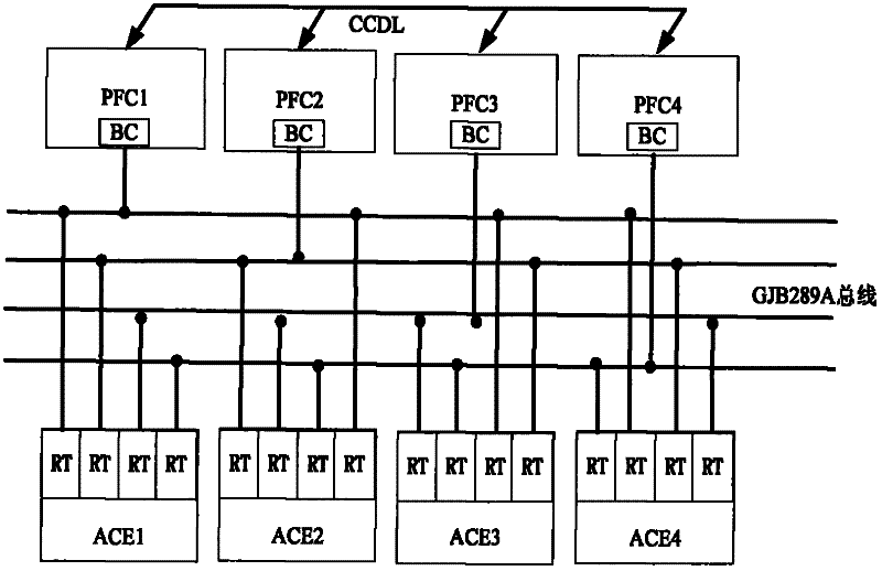
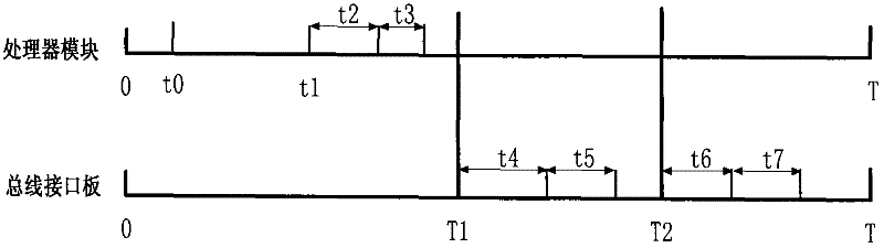
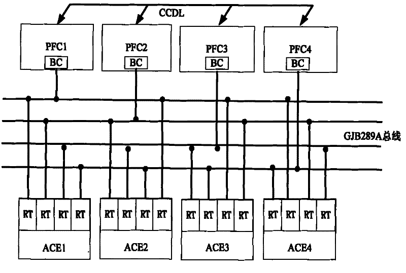
[0015] For the connection relationship of the distributed redundancy flight control system, see figure 1 As shown, the main flight control computer PFC adopts the architecture scheme of 4-redundancy configuration. The 4-redundancy main flight control computer and the 4-redundancy airborne equipment ACE are connected through the GJB289A bus. The main flight control computer is BC, and ACE is RT. A PFC takes the ARINC-659 serial backplane bus as the core, and the processor module and the bus interface board are connected to the ARINC-659 bus in the form of resources. For the planning of the bus time window, see figure 2 , the bus interface board performs data transmission on the GJB289A bus according to the ARINC-659 bus time window plan, and the specific implementation steps are as follows:

[0016] 1. Redundant flight control computer channels and each functional module in the computer channel are base...


PUM


Abstract

The invention belongs to a distributed redundancy control system communication technology, and relates to a method for improving the distributed redundancy control system communication technology. The method is characterized in that: functional characteristics and time sequence arrangements of each set of equipment in the distributed control system are planned and considered according to a method for planning a bus time window in advance, so that signal transmission between a main processor and onboard equipment is ensured to be finished within a bus period. The data transmission timeliness is improved, and the time delay of data transmission of the distributed redundancy control system is reduced; and therefore, the instantaneity of the whole system is guaranteed.

Description

technical field [0001] The invention belongs to the communication technology of a distributed redundancy control system. It relates to an improved method of communication technology in a distributed redundancy control system. Background technique [0002] The layout of the existing fly-by-wire flight control system is mostly a centralized structure, that is, the airborne equipment is directly connected to the computer, and the data receiving and sending between the airborne equipment and the processor is carried out by task triggering. Data transmission can only be performed during scheduling, which is greatly affected by the number and priority of tasks. The centralized structure relies too much on the central processor, and cannot complete timely information processing and accurate and effective decision-making and control. The processor is easy to become the bottleneck of system design; at the same time, the centralized control structure obviously lacks the flexibility a...

Claims


Application Information

Patent Timeline
Patent Type & Authority Applications(China)
IPC IPC(8): G05B9/03
Inventor 谯婷婷屈华敏杜乃鹏赵淑利
Owner FLIGHT AUTOMATIC CONTROL RES INST
Why Eureka
Try Eureka