
Redundant data processing system of intelligent substation

A smart substation and redundant data technology, applied in information technology support systems, electrical components, circuit devices, etc., can solve the problems of non-unique and inconsistency of primary equipment information, and achieve the effect of ensuring uniqueness

Active Publication Date: 2012-07-11
长园深瑞继保自动化有限公司
View PDF3 Cites 13 Cited by
  • Summary
  • Abstract
  • Description
  • Claims
  • Application Information

AI Technical Summary

Problems solved by technology

However, due to the dual measurement and control configuration introduced in the measurement, control and protection configuration of the primary equipment in the substation system, the information of the primary equipment is not unique, especially when one of the measurement and control devices is faulty or communication failure, the event information of the same primary equipment may even be different. If there is an inconsistency, the user needs to check the authenticity of the device information

Method used


Image

  • Redundant data processing system of intelligent substation
  • Redundant data processing system of intelligent substation
  • Redundant data processing system of intelligent substation

Examples


Embodiment 1

[0067] Embodiment 1, the intelligent substation redundant data processing system of the present invention is implemented by using X86Sun server, solaris10 operating system, Qt3.3 version, and C++ programming language to test the intelligent substation with a voltage level of 220kV.

[0068] The specific code is as follows:

[0069] Function name: SwitchMasterUnitIDAndMasterSigID;

[0070] Function: switch master-slave device and master-slave signal;

[0071] Input: the ID of the pairing relationship table of the dual measurement and control devices;

[0072] Output: None.

[0073]

[0074]

[0075] Function name: SwitchMasterYxID;

[0076] Function: switch the master-slave remote signaling corresponding to the pointer of the remote signaling signal pairing relationship table;

[0077] Input: remote signaling signal pairing relationship table pointer;

[0078] Output: None.

[0079]

[0080]Function name: SwitchMasterUnitID;

[0081] Function: Perform master-sla...

Embodiment 2

[0086] Embodiment 2 adopts solaris x86 system, kdevelop integrated environment, and QT3.3.8 version C++ graphical interface program framework.

[0087] The switching of telemetry master-slave signals can also be realized by the same method.

[0088] Such as Figure 7 As shown, for the automatic switching master-slave device, the system introduces a state machine and an optional delay time parameter (which can be 0). Realize automatic switchover of master-slave device with delay.

[0089] When the system is executing remote control commands, five-defense simulation operations or programmed operations, it will temporarily block automatic switching and prohibit manual switching.

[0090] The specific process refers to the following functions:

[0091] Function name: run;

[0092] Function: Process the master-slave device, master-slave signal automatic switching, and judge whether it is temporarily blocked;

[0093] input: None;

[0094] Output: None.

[0095]

[0096] ...


PUM


Abstract

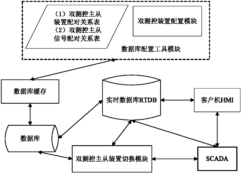
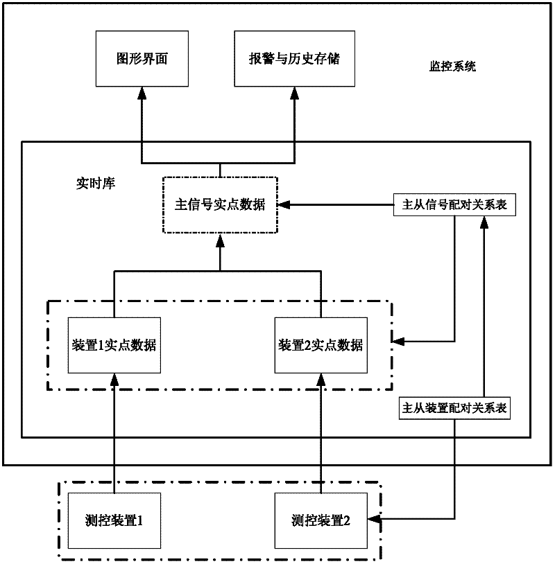
The invention discloses a redundant data processing system of an intelligent substation, which guarantees uniqueness of information of primary equipment which is concern of substation users. The redundant data processing system of the intelligent substation is formed by a data base configuration tool module, a real-time data base, a data collection and monitoring control system, a double-measurement-control master-slave device switching module, a data base buffering module, a data base and a client module. Compared with the prior art, by introducing a double-measurement-control master-slave device pairing relation table and a double measurement and control master-slave signal pairing relation table, correspondence of real signals of a double measurement and control master data source measuring and controlling device to the primary equipment is achieved, the fact that the measuring and controlling device is a master data source device is guaranteed, the information of the primary equipment comes from master real signals under the master data source device, and accordingly the uniqueness of the information of the primary equipment is guaranteed. The method does not change a structure of an existing substation automation system and does not cause extra loads to an existing monitoring system.

Description

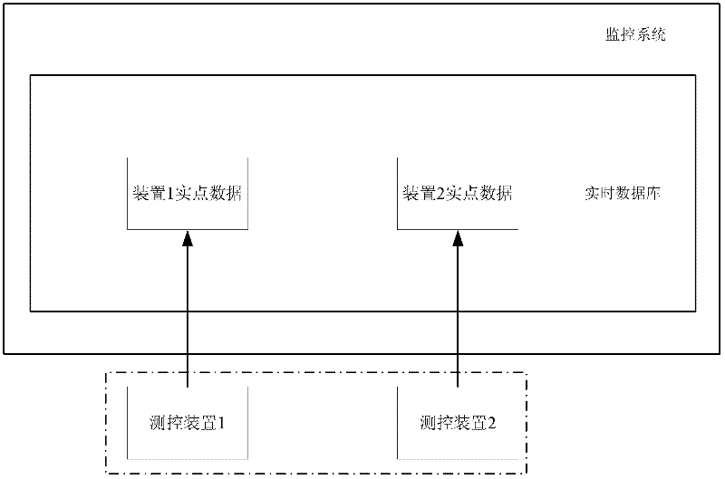
technical field [0001] The invention relates to a substation monitoring system, in particular to a redundant data processing system of an intelligent substation. Background technique [0002] With the emergence of 220kV and above voltage level substation protection, measurement and control integrated devices, according to the dual configuration principle of power system protection devices in substation measurement, control and protection configuration, measurement and control devices also need dual configuration. Such as figure 1 As shown, if the monitoring system of the substation system does not make corresponding improvements, the usual practice is to send the data of the two measurement and control devices into the monitoring system. Therefore, the actual primary equipment is instantiated twice in the monitoring system. The monitoring system corresponds to two measurement and control devices respectively. As a result, all primary equipment information is stored in two ...

Claims


Application Information

Patent Timeline
Patent Type & Authority Applications(China)
IPC IPC(8): H02J13/00
CPCY04S10/40
Inventor 孙一民徐奕信黎强侯林
Owner 长园深瑞继保自动化有限公司
Learn More