

Power supply device for taking electricity from high-voltage side in induction manner
A technology of inductive power taking and power supply device, applied in circuit devices, emergency protection circuit devices, emergency protection devices with automatic disconnection, etc., can solve problems such as burning loads, damage to protection circuits, economic losses, etc., and achieve high economic benefits. , The application prospect is good, the effect of ensuring safety and stability
- Summary
- Abstract
- Description
- Claims
- Application Information
AI Technical Summary
Problems solved by technology
Method used
Image

Examples
Embodiment 1
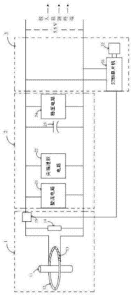
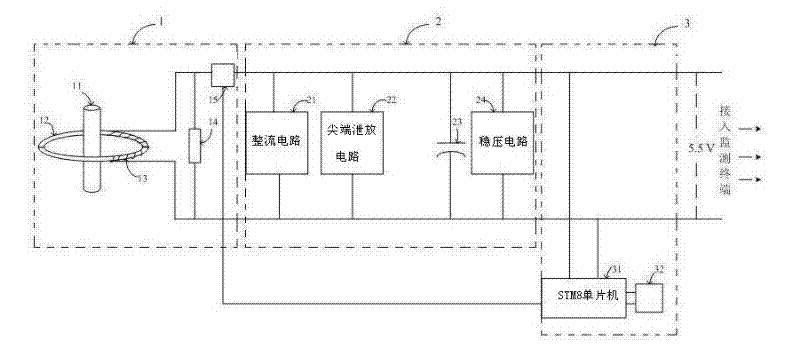
[0015] Embodiment 1, with reference to Figure 1-2 , a power supply device for inductively taking power from a high-voltage side: it includes a power taking module 1, a power conditioning module 2 and an intelligent protection module 3;
[0016] The power taking module 1 includes a primary bus 11, a current transformer core 12, a secondary coil 13, a sampling resistor 14, and a single-pole double-throw relay 15; the primary bus 11 passes through the current transformer core 12; The secondary coil 13 is wound on the current transformer magnetic core 12, connected in parallel with the sampling resistor 14, and connected in series with the SPDT relay 15;
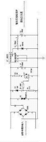
[0017] The power conditioning module 2 includes a rectifier circuit 21, a tip discharge circuit 22, a ripple filter capacitor 23, and a voltage stabilizing circuit 24, and each circuit is connected in series in sequence; the tip discharge circuit 22 includes a voltage regulator tube, a voltage regulator tube After being connec...
PUM
 Abstract
Description
Claims
Application Information