A test system for radio frequency index
A test system and index technology, applied in transmission systems, transmitter monitoring, transmission monitoring and other directions, can solve problems such as low efficiency, and achieve the effect of eliminating the impact of RRU performance and improving test efficiency.
- Summary
- Abstract
- Description
- Claims
- Application Information
AI Technical Summary
Problems solved by technology
Method used
Image

Examples
Embodiment 1
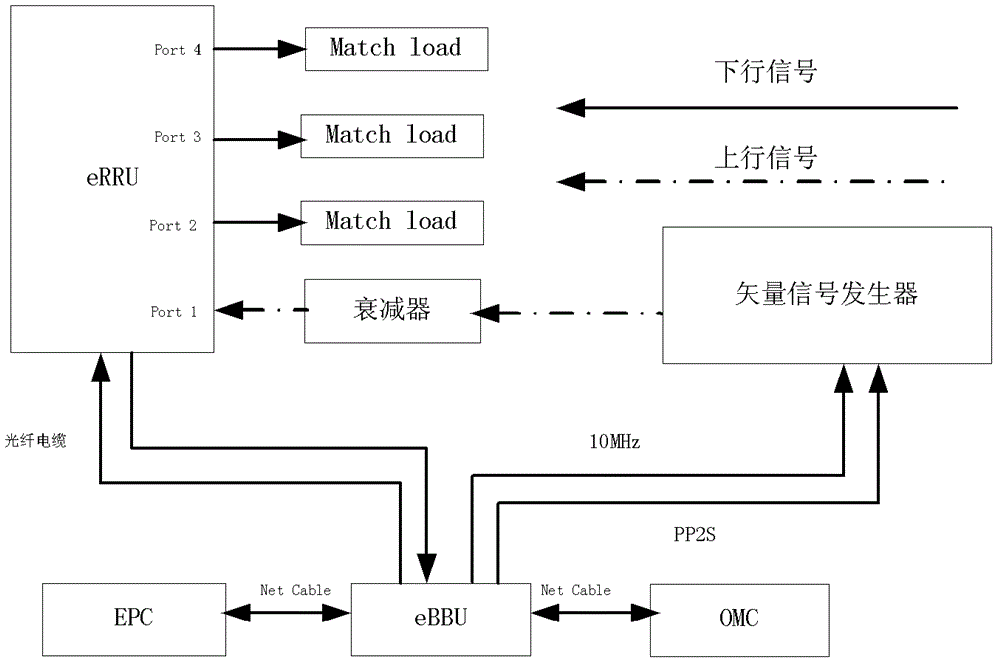
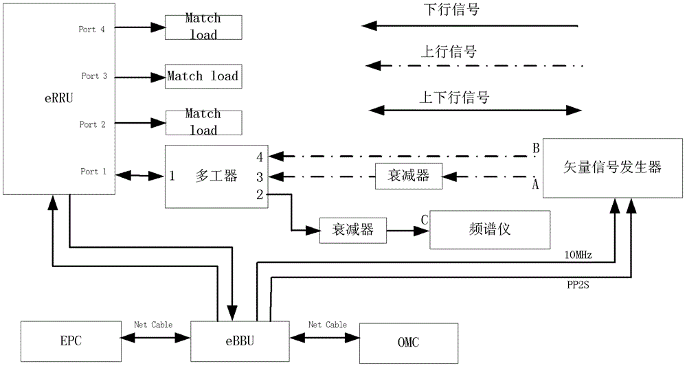
[0041] Carry out the test system that the uplink and downlink indicators are tested simultaneously as shown in Figure 3 (a), the composition of the test system of the present embodiment is as follows:
[0042] The common port (Port1) through which the downlink and uplink signals of a multiplexer pass is connected to an antenna port of the eRRU (evolved RRU), and the bandpass filter interface (Port2) of the multiplexer is connected to an attenuator, which is connected to the attenuator A spectrum analyzer is connected, and the two band rejection filter interfaces (Port3 and Port4) of the multiplexer are respectively connected with two output ports of a vector signal generator.
[0043] The EPC in the figure is the core network), the eBBU is the base station resource pool, and the OMC is the operation and maintenance center.
[0044] In this embodiment, the downlink signal of the base station passes through Port1 to Port2 of the triplexer, and then passes through the attenuator ...
Embodiment 2
[0049] Embodiment 2, when the interference signal falls outside the TX frequency band, the test system for testing the block index under the TX rated power is shown in FIG. 3( a ).
[0050] In this embodiment, the TX signal reaches the rated power, and the signal source sends out an interference signal that is greater than the predetermined power and does not fall within the TX frequency band, so as to perform the blocking index test under the condition that the downlink signal reaches the rated power.
[0051] In this embodiment, the attenuator can be adjusted so that the power entering the spectrum analyzer is within the allowable range, so that the rated power of the TX will not cause damage to the spectrum analyzer.
[0052] Due to the stop band of the TX signal in the multiplexer, the TX rated power cannot pass through Port1 to Port3 and Port4 to cause damage to the signal source, so the TX high-power signal will not enter the signal source.
[0053] In this embodiment, t...
Embodiment 3
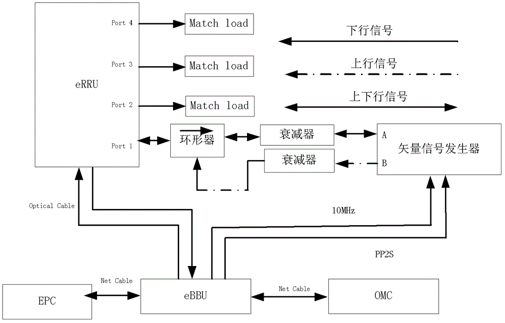
[0054] Embodiment 3, when the interference signal falls in the TX frequency band, test the test system of the block index under the TX rated power, as shown in Figure 3 (b), the structure of the test system of the present embodiment is as follows:
[0055] The port (Port1) through which the downlink and uplink signals of a multiplexer pass is connected to an antenna port of the RRU, the bandpass filter interface (Port2) of the multiplexer is connected to a circulator, the circulator is connected to an attenuator, and the attenuator Connect with a spectrum analyzer, one port (A) of the vector signal generator is connected with the band-stop filter interface (Port3) of the multiplexer through the attenuator, and the other port (B) of the vector signal generator is connected with the circulator , the other band-stop filter interface (Port4) of the multiplexer is connected to a matching load.
[0056] In this embodiment, the downlink signal of the base station passes through Port1...
PUM
 Abstract
Description
Claims
Application Information