Hydraulic excavator attachment control device

A technology for hydraulic excavators and auxiliary equipment, which is used in mechanical equipment, fluid pressure actuating devices, earth movers/shovels, etc. question

Inactive Publication Date: 2012-07-11
NIHON KENKI CO LTD
View PDF8 Cites 4 Cited by
  • Summary
  • Abstract
  • Description
  • Claims
  • Application Information

AI Technical Summary

Problems solved by technology

[0009] However, in the prior art described above, the problem that the operator forgets to switch from the normal mode to the accessory mode is not considered, and the accessory is operated in the normal mode that is not set according to the type of accessory. As a result, the auxiliary equipment will be used in a state exceeding the specification, and there is a possibility that the auxiliary equipment and other hydraulic machinery may fail or the life may be shortened.
In addition, since foreign matter such as dust may be mixed into the return oil, it is preferable to allow the return oil to flow directly back to the oil tank without passing through the control valve for auxiliary equipment such as a rock crusher. When the auxiliary equipment such as the rock crusher is operated in the normal mode of flowing back into the oil tank, there is a possibility that the valve column is stuck (spool stick) due to dust, etc., and the state exceeds the specification Similarly, when using auxiliary equipment, there is a possibility that the auxiliary equipment and other hydraulic equipment may fail or reduce their life.

Method used


Image

  • Hydraulic excavator attachment control device
  • Hydraulic excavator attachment control device
  • Hydraulic excavator attachment control device

Examples


no. 1 approach

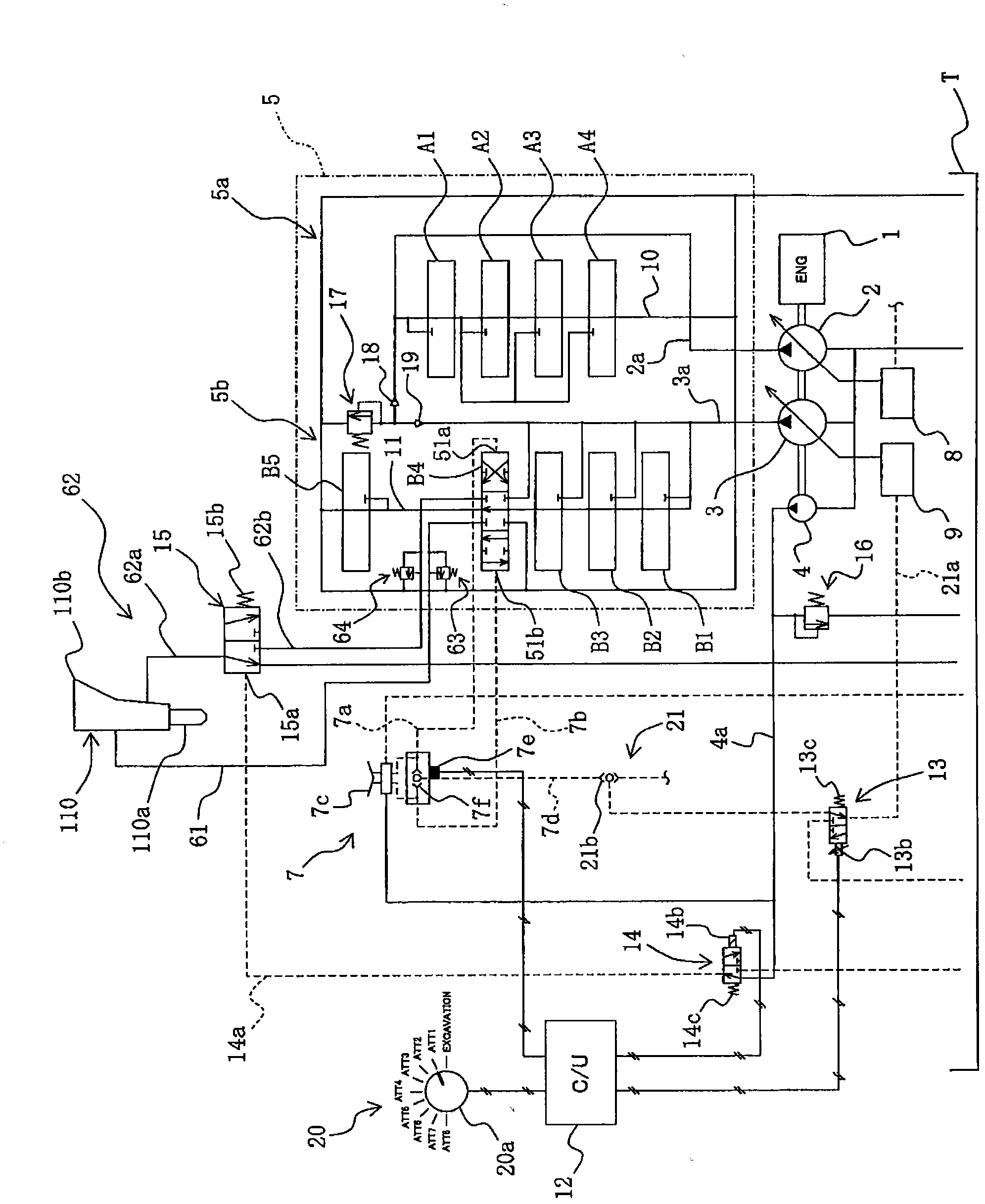
[0030] figure 1 It is a diagram schematically showing the overall configuration of a hydraulic circuit system of a hydraulic excavator having an attachment control device according to a first embodiment of the present invention.

[0031] exist figure 1 Among them, the hydraulic circuit system of the hydraulic excavator has: a prime mover 1 such as an engine; Driven fixed-capacity pilot pump 4; control valve unit 5 connected to the first and second hydraulic pumps 2, 3; rock crusher 110 as an accessory device connected to the control valve unit 5; connected to the control valve The multiple hydraulic actuators on the unit 5 include boom hydraulic cylinders 111, arm hydraulic cylinders 112, bucket hydraulic cylinders 113, and swing motors 107 (also refer to Figure 5 ); an operating pedal device 7 (accessory equipment operating mechanism) for operating ancillary equipment (a rock crusher 110 in this embodiment); A plurality of operating devices (not shown simultaneously) of t...

no. 2 approach

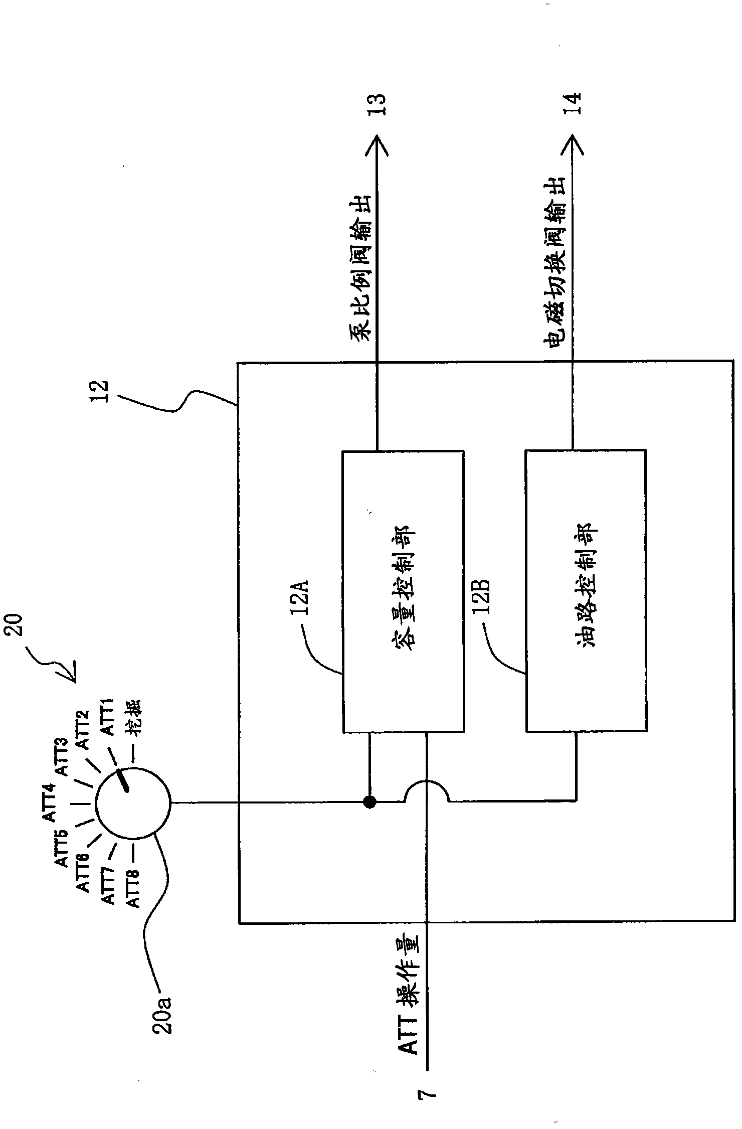
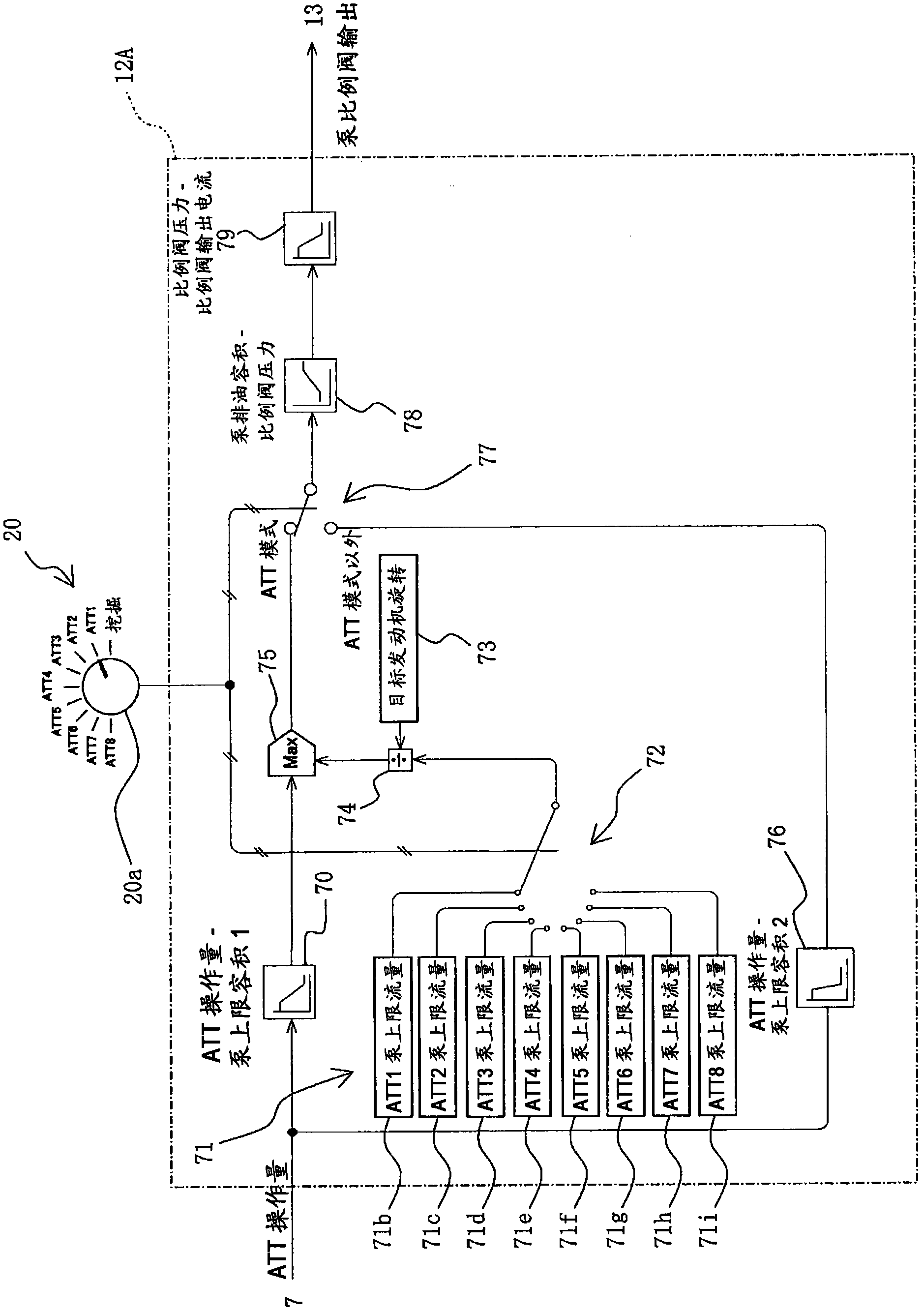
[0090] use Figure 6 ~ Figure 9 A second embodiment of the present invention will be described. Figure 6 It is a figure which schematically shows the whole structure of the hydraulic circuit system of the hydraulic excavator provided with the attachment control apparatus of this embodiment. Figure 7 is a block diagram showing the processing content of the control unit of this embodiment, Figure 8 It is a detailed figure showing the processing contents of the pump capacity control unit, Figure 9 It is a detailed figure which shows the processing content of a pilot pressure control part. In addition, in Figure 2 ~ Figure 4 In , for the sake of explanation, the accessory equipment selection means 20 are also shown together. In the figure, with Figure 1 to Figure 5 The same reference numerals are assigned to the same components shown in the drawings, and description thereof will be omitted.

[0091] exist Figure 6 Among them, the hydraulic circuit system of the hydra...


PUM


Abstract

Disclosed is a hydraulic excavator attachment control device comprising a hydraulic circuit that is provided with a hydraulic pump (3); a plurality of actuators including the actuator for a breaker (110) which is an attachment; and a plurality of flow control valves including a flow control valve (B4) for the attachment, this flow control valve (B4) being switched by means of operating pilot pressure from an operating pedal device (7), and supplying discharged oil from the hydraulic pump (3) to the actuator for the attachment. When the operating pedal device (7) is operated, with an attachment mode not selected by an attachment selecting device (20), the action of the actuator for the attachment is restricted. Due to the above, if an operator forgets to switch from a normal mode to the attachment mode, resulting in the attachment being operated, it is possible to prevent the failure and life reduction of the attachment and other hydraulic devices.

Description

technical field [0001] The present invention relates to an attachment control device for a hydraulic excavator, and more particularly to an attachment control device for a hydraulic excavator having a hydraulic circuit for attachments mounted on a front working machine of the hydraulic excavator. Background technique [0002] In a hydraulic excavator as a construction machine, in addition to installing a highly versatile bucket to carry out excavation operations, etc., the front end of the front working machine can also be equipped with auxiliary equipment such as a breaker or a crusher. Perform various tasks instead of buckets. [0003] Among the attachments installed on the front working machine, the specifications such as the pressure and flow rate of the pressure oil are determined according to the type, and it is necessary to change the settings of the hydraulic circuit and the like according to the type of attachment installed on the front working machine. [0004] As...

Claims


Application Information

Patent Timeline
IPC IPC(8): E02F9/22E02F9/24F15B20/00
CPCE02F9/2282E02F3/966E02F9/2292E02F9/2228E02F3/963E02F9/2296E02F9/22E02F9/24F15B20/00
Inventor 东宏行中村刚志冈野康雄石川广二
Owner NIHON KENKI CO LTD
Why Eureka
Try Eureka