Device for the pulsed release of an amount of fluid which can be stored in an accumulator housing

A storage box and fluid volume technology, which is applied in the direction of fluid pressure actuators, transmission device control, fluid pressure actuator system components, etc., can solve the problems of consuming manufacturing structure space requirements, and achieve the effect of simple structure

Active Publication Date: 2012-07-11
HYDAC TECH GMBH
View PDF7 Cites 2 Cited by
  • Summary
  • Abstract
  • Description
  • Claims
  • Application Information

AI Technical Summary

Problems solved by technology

This known device is at least expensive to manufacture or requires a significant installation space requirement

Method used


Image

  • Device for the pulsed release of an amount of fluid which can be stored in an accumulator housing
  • Device for the pulsed release of an amount of fluid which can be stored in an accumulator housing
  • Device for the pulsed release of an amount of fluid which can be stored in an accumulator housing

Examples


Embodiment Construction

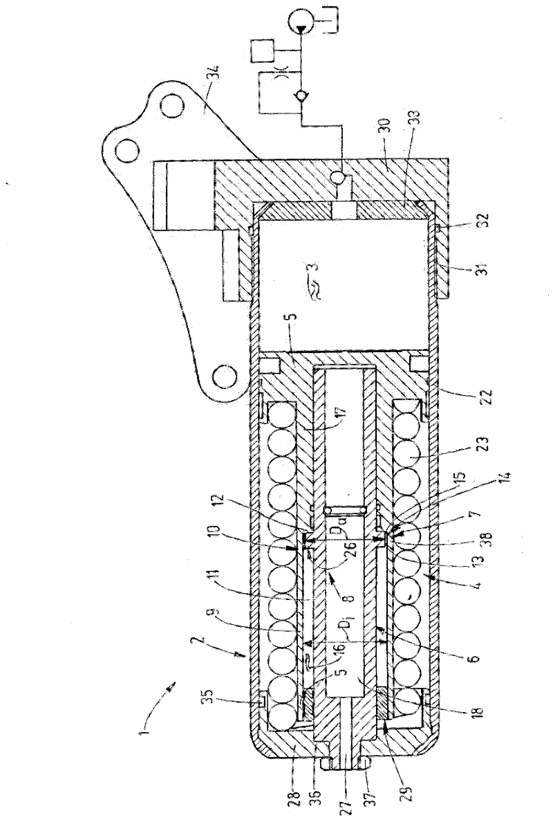
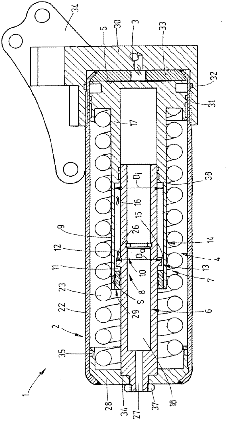
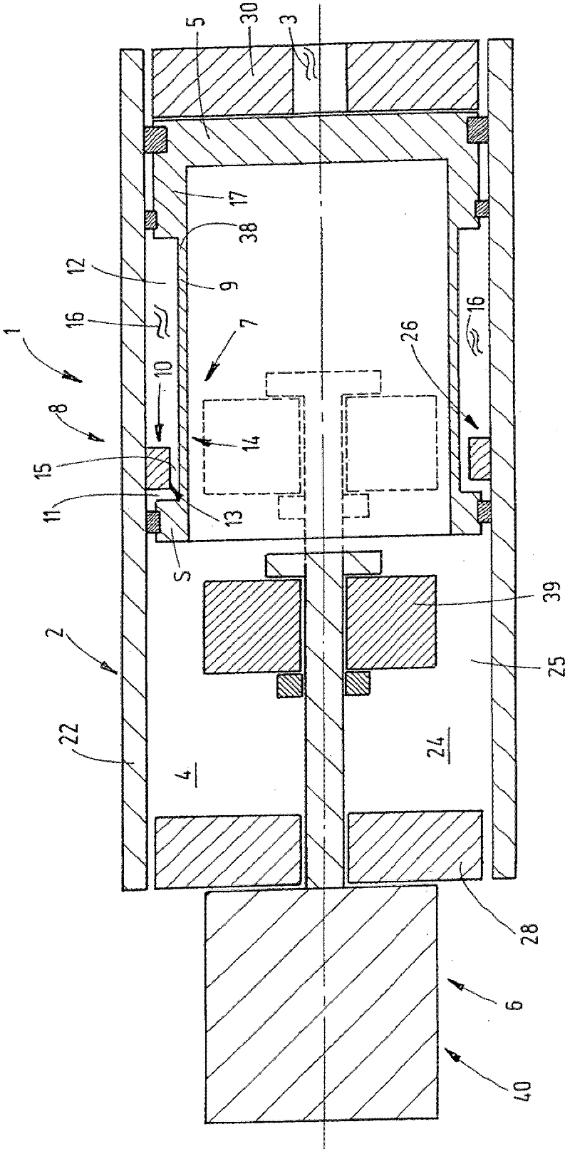
[0025] exist figure 1 The device 1 for pulse-like release of a fluid quantity 3 that can be stored in a storage tank 2 is shown in longitudinal section. The device 1 is used for storing working fluid of consumers of a hydraulic system (not shown), for example for storing and pulsating hydraulic oil for the working cylinders of an automatic transmission of a passenger car. The cylindrical storage box 2 has a first energy store 4 configured as a cylindrical compression spring. The accumulator 4 is used to load the piston 5 with a pressure sufficient to move the piston 5 from its pre-compressed position (eg figure 1 shown) to the position where fluid volume 3 is drained from storage tank 2 (see figure 2 ). Fluid volume 3 at piston 5 figure 1 The indicated position is fed under pressure into the storage tank 2 by means of a fluid conveying device known per se, for example a rotary pump. After the filling process, the piston 5 is held in the preloaded position shown by the lo...


PUM


Abstract

Device for the pulsed release of an amount of fluid (3) which can be stored in an accumulator housing (2). A device for the pulsed release of an amount of fluid which can be stored in a storage housing (2) is characterized in that a locking device (7) is formed by a piston-cylinder arrangement (8) having a cylinder housing (9) that is subdivided into a first working chamber (11) and a second working chamber (12) by a working piston (10), an electrorheological or magnetorheological valve (14) in the form of a gap (15) or an opening being arranged between the working chambers (11, 12) in the circumference (13) of the working piston (10) or in the working piston (10) as such.

Description

technical field [0001] The invention relates to a device for the pulsed release of a fluid quantity that can be stored in a storage tank, in particular for the start-stop function in an automatic transmission, the device having a piston supported on a first accumulator, the piston movable within the storage tank and together with the storage tank limit the amount of fluid that can be contained, and the piston is controlled by the operating device and released by the locking device to discharge the fluid volume from the storage tank in pulses, wherein the locking device holds the piston in the The pre-compressed position of the piston, and the locking device in the disengaged position is actuated by the operating device to release the piston. Background technique [0002] In modern motor vehicles the internal combustion engine is switched off in suitable operating states for reasons of fuel saving and minimization of pollutant emissions. Nevertheless, in order to be able to ...

Claims


Application Information

Patent Timeline
Patent Type & Authority Applications(China)
IPC IPC(8): F16H61/00
CPCY02E60/15F15B2201/40F16H61/0021F15B1/24F15B2201/21F16H2061/0034F15B2201/31F16H2312/14F15B21/065Y02E60/16Y10T74/20024F16H61/0025
Inventor N·朗格N·韦伯
Owner HYDAC TECH GMBH
Why Eureka
Try Eureka