Surface-emitting LED cover, lighting device and display device

一种LED照明、LED光源的技术,应用在照明装置、照明装置的零部件、照明和加热设备等方向,达到成形性提高、脱模容易的效果

Active Publication Date: 2012-07-11
SATO LIGHT INDAL +1
View PDF7 Cites 0 Cited by
  • Summary
  • Abstract
  • Description
  • Claims
  • Application Information

AI Technical Summary

Problems solved by technology

However, due to the strong directivity of LEDs, it is difficult to obtain uniform brightness distribution on a wide range of surfaces using a single LED light source

Method used


Image

  • Surface-emitting LED cover, lighting device and display device
  • Surface-emitting LED cover, lighting device and display device
  • Surface-emitting LED cover, lighting device and display device

Examples


Embodiment 1

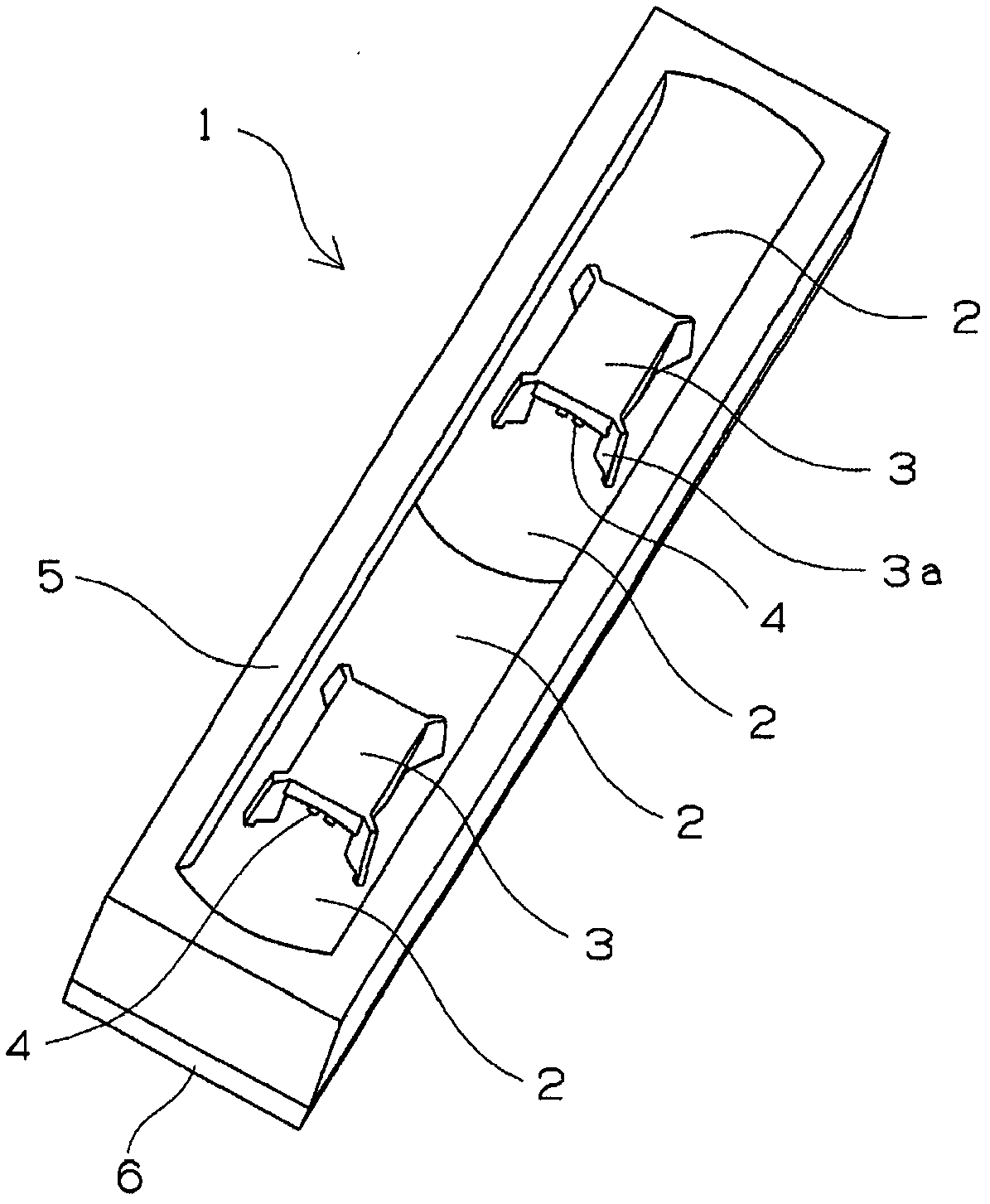
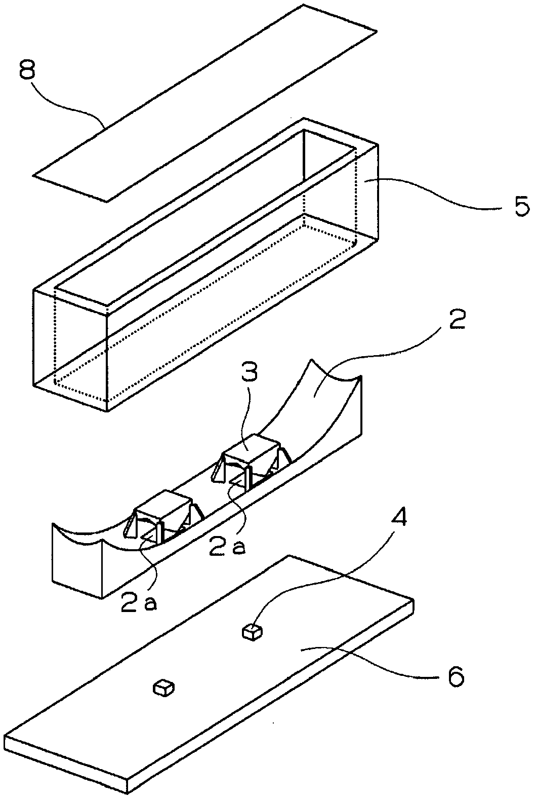
[0136] A LED surface-emitting cover with a main reflector and a sub-reflector is disposed in a casing with a surface-emitting opening of 4×26mm in size and a height of 7mm integrally formed with a highly reflective resin material.

[0137] As for the LED light source, two surface-mounted LED light sources with a directivity of 160 degrees were used at intervals of 9 mm. In addition, about the sub-reflector, used Figure 9 The reflected shape is shown.

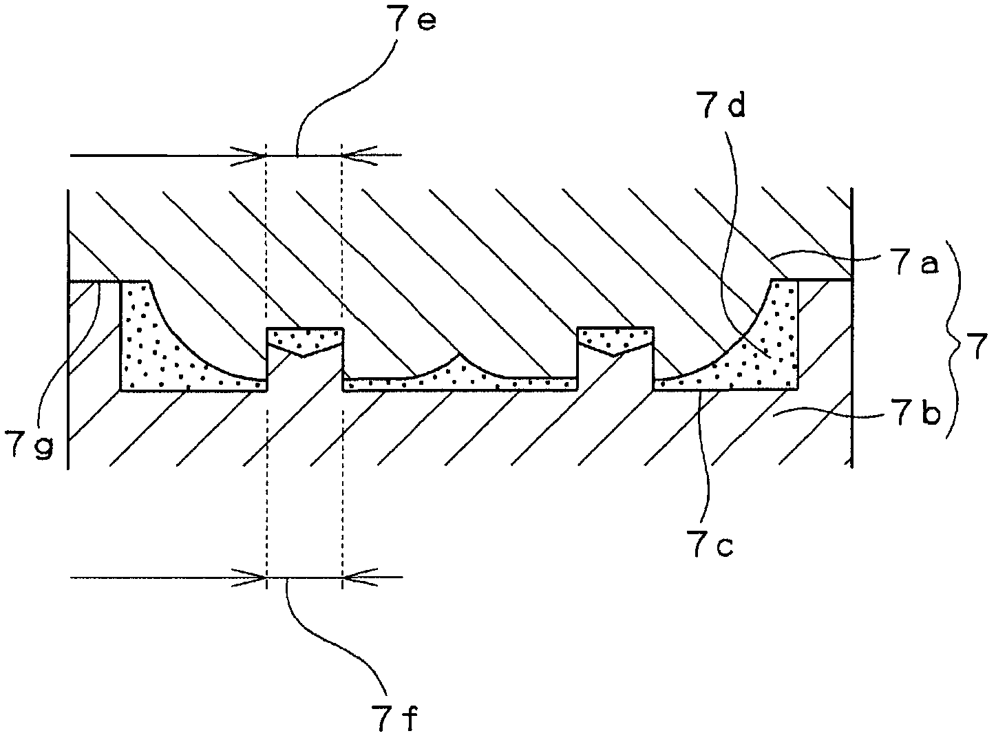
[0138] The distance from the reflective surface of the sub-reflector to the LED light source is set at 0.2-0.7 mm. In addition, the inclination angle β of the sub-reflector in the Y direction (longitudinal direction of the opening) section in which the LED light sources are arranged at approximately equal intervals is 120 to 140 degrees, and the angle γ in the orthogonal X section is 200 to 240 degrees. degree sub-reflector.

[0139] As for the reflection surface of the main reflector, an angled curvature is formed by a free...

Embodiment 2

[0146] A diffusion film (manufactured by KIMOTO Corporation, model D207, light transmittance 59%) was attached to the front surface of the housing of the LED lighting device obtained in Example 1 using a double-sided tape.

[0147] The obtained lighting device exhibited surface emission in which uniform luminance was obtained over the entire light emitting surface.

Embodiment 3

[0149] With respect to the diffusion film used in Example 2, semi-transmissive ink for lowering the transmittance to match the transmittance of the low-brightness portion was printed in layers on the high-brightness portion when no light-diffusion film was used. The layer-printed diffusion film was pasted on the front surface of the housing of the LED lighting device obtained in Example 1 by ultrasonic welding.

[0150] The obtained lighting device exhibited surface emission in which uniform luminance was obtained over the entire light emitting surface.

[0151] In addition, in order to reduce the transmittance so that the light-diffusing film is not used in the part with high brightness so as to match the part with low brightness, a layered non-dotted layer is used so that unevenness does not occur during lighting. Also in the case of a diffusion film printed with a non-transmissive ink, surface emission with uniform brightness over the entire light emitting surface is simila...


PUM

PropertyMeasurementUnit
visible light transmittanceaaaaaaaaaa

Abstract

The present invention relates to a surface-emitting LED cover, a lighting device and a display device. A surface-emitting LED cover (1) comprises a molded resin body, and is provided with a main reflector (2) for reflecting light toward the front of the surface light source, and sub-reflectors (3) that have a reflective surface for reflecting light from an LED light source (4) in the direction of the main reflector. The main reflector has openings (2a) in which an LED light source can be disposed, and is formed so as to have a curved surface that directs reflected light coming from the sub-reflector in the direction toward the front of the surface light source. The sub-reflectors are disposed above the openings formed on the main reflector, and the reflective surface of each sub-reflector is positioned at a slant to the aforementioned opening surface. Thus, a lighting device is provided that is capable of surface emission through a simple method, even when using an LED light source that has strong directionality.

Description

technical field [0001] The present invention relates to an LED surface-emitting cover, a lighting device and a display device using the LED surface-emitting cover. Background technique [0002] Illumination devices using highly directional light sources such as light emitting diodes (hereinafter referred to as LEDs) are being put into practical use. However, since LEDs have strong directivity, it is difficult to obtain uniform luminance distribution over a wide range of surfaces using a single LED light source. [0003] Conventionally, as a direct-type surface light source device arranged directly below a liquid crystal display panel, there is known a surface light source device (Patent Document 1) in which a light source insertion portion is recessed on the rear surface of a light guide plate, and a light source insertion portion is inserted into the light source insertion portion. The light source is accommodated in the middle, and a light reflection surface is provided i...

Claims


Application Information

Patent Timeline
Patent Type & Authority Applications(China)
IPC IPC(8): F21V7/09F21S2/00F21V7/00F21Y101/02
CPCG02B19/0061F21S2/00F21V7/09G02B19/0028H01L33/58F21V7/00
Inventor 土井元裕石井龙仁汤浅英治
Owner SATO LIGHT INDAL
Why Eureka
Try Eureka