
Measuring instrument and method for determination of the properties of an item and its surface

A characteristic and detector technology, applied in the field of measuring instruments, can solve problems such as changes in reflected light intensity and distance angles

Inactive Publication Date: 2012-07-11
LEMMAI TECH CO LTD
View PDF9 Cites 27 Cited by
  • Summary
  • Abstract
  • Description
  • Claims
  • Application Information

AI Technical Summary

Problems solved by technology

It can also happen that the focused light from the radiation source does not reach the proper location on the surface being measured, so the intensity of the reflected light may change
These defects can be caused by, for example, changes in the distance and / or angle of the fluttering surface relative to the detector

Method used


Image

  • Measuring instrument and method for determination of the properties of an item and its surface
  • Measuring instrument and method for determination of the properties of an item and its surface
  • Measuring instrument and method for determination of the properties of an item and its surface

Examples


Embodiment Construction

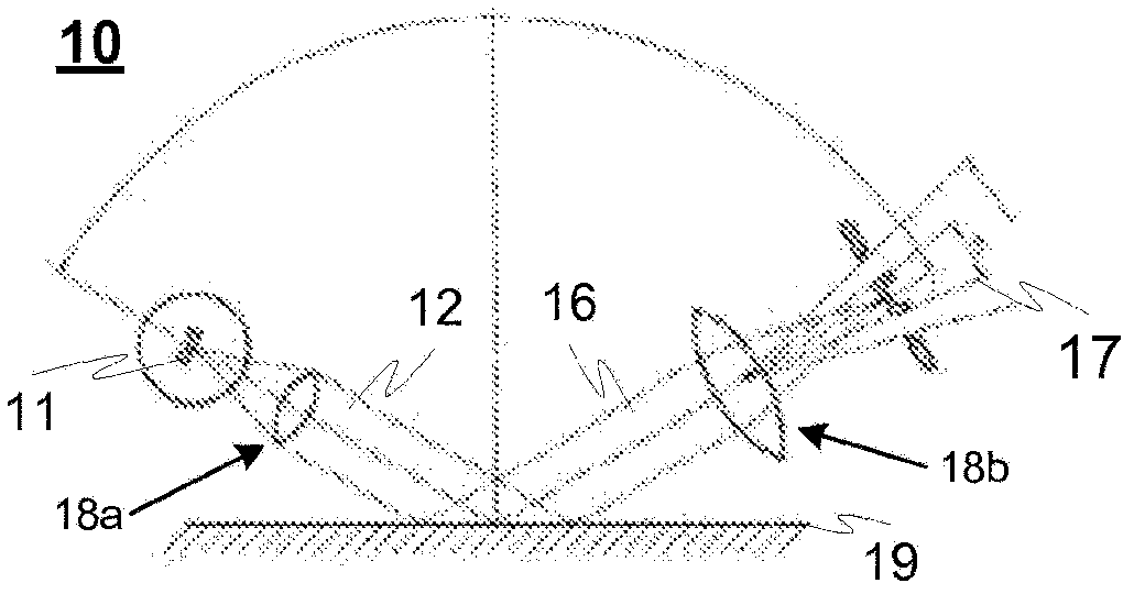
[0051] figure 1 A gloss measurement geometry 10 according to the gloss standard ISO 2813 is illustrated, wherein a light beam 12 generated by a light source 11 is directed by means of converging means 18a, such as a lens, to a surface 19 being measured. The light rays are reflected from the surface 19 in the direction of the mirror geometry 16 in which they are concentrated to the light radiation detector 17 by means of converging means 18b, eg lenses. The detector 17 measures the intensity of the reflected light ray 16 and determines the glossiness of the surface 19 being measured based on the intensity of the light ray 16 .

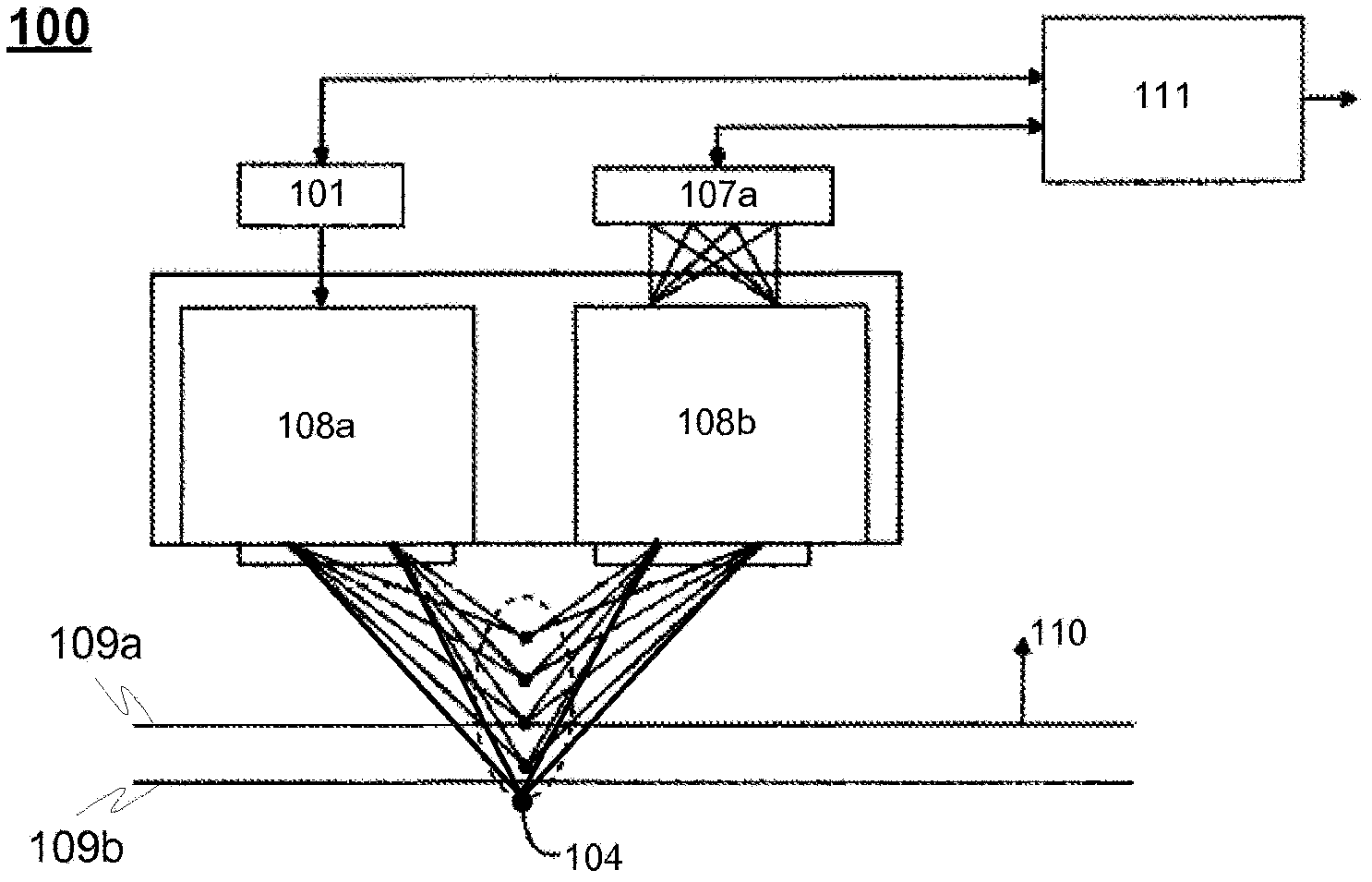
[0052] Figure 2a An exemplary measuring device 100 according to an embodiment of the invention is illustrated, wherein the system comprises an optical radiation source 101 for emitting optical radiation 102 (eg white light or other moderately continuous spectral light) towards an optical radiation processing unit 108a . The optical radiation process...


PUM


Abstract

A measurement device for the determination of the characteristics of the object's surface by means of the optical radiation, wherein a measurement device comprises an optical radiation source and a detector to receive the radiation reflected from the surface being measured. In addition, a measurement device comprises an emitted optical radiation processing unit, which is adjusted to split optical radiation emitted by an optical source into separate wavelengths and to direct said separate wavelengths to the object being measured in a direction, that differs from the normal of the surface being measured so, that at least the shortest and the longest wavelengths of said wavelengths are focused on different halves and different heights of the measured object's surface, in the direction of the normal of the surface being measured. In addition, a measurement device comprises a reflected optical radiation processing unit, which is adjusted to receive an optical radiation reflected from the measured object at least in the direction of a specular reflection, which differs from the normal of the surface being measured, and to direct received optical radiation to said detector. Still further, the measurement device is adjusted to analyze an electric signal produced by the detector and proportional to the intensity of the radiation focused thereto, and to further determine a surface gloss (gloss degree) and / or thickness characteristic property of the measured object, based on the intensity of its wavelength, the focus point of which was located on the measured surface, and which wavelength was the strongest reflected from that point to the detector in the specular geometry.

Description

technical field [0001] The present invention relates to measuring instruments and methods, particularly those for measuring surface properties of articles such as gloss, refractive index and / or thickness. Background technique [0002] The control of the properties of the surface of an item (eg monitoring the quality of the surface of paper, metal and various films) as well as the control of the thickness of the surface is a critical part during eg process control and product quality control. A well known and commonly used parameter for surface quality characterization is gloss. Optical measurement of surface gloss is commonly used and extensively documented, for example in ISO standard 2813 "Paints and Varnishes-Determination of specular gloss if nonmetallic paint films at 20° 60° and 80°". Currently, eg in the steel industry, gloss is mainly determined in the laboratory in the so-called off-line mode by using separate point-like sensors. Determining gloss parameters by us...

Claims


Application Information

Patent Timeline
Patent Type & Authority Applications(China)
IPC IPC(8): G01N21/57G01B11/06
CPCG01N21/57G01B11/065G01B11/0633G01B2210/50G01N21/41G01B11/0608G01B11/0691G01B2210/44G01B11/0625G01N21/55
Inventor 卡里·涅梅莱海莫·凯雷宁
Owner LEMMAI TECH CO LTD
Learn More