High negative pressure non-clogging drainage tube

A drainage tube, non-blocking technology, used in catheters, other medical devices, hypodermic injection devices, etc., can solve the problems of not easy to pull out, easy to form adhesion, untimely drainage, etc., to avoid adhesion and relieve pain.

Inactive Publication Date: 2012-07-18
朱新生
View PDF6 Cites 5 Cited by
  • Summary
  • Abstract
  • Description
  • Claims
  • Application Information

AI Technical Summary

Problems solved by technology

The double cannula has the functions of postoperative drainage, wound washing, wound administration, and prevention of built-in drainage tube blockage. It is the most complete and advanced postoperative drainage tube at present, but it still has the following defects: 1) It cannot Solve the key "bottleneck" problem that affects the drainage effect - drainage tube blockage (Note: Although the built-in drainage tube can be replaced, the cannula drainage hole of the built-in cannula that is set outside the built-in drainage tube will still be blocked); 2) When using In negative pressure active drainage, the cannula drainage needs air or medicinal liquid to continuously enter the drainage area, which is easy to form local cavities, and also increases the risk of bacteria in the air entering the drainage area; 3) only gravity or low load can be used. The biggest disadvantage of gravity and low negative pressure drainage is that the drainage is not timely and thorough, and it is difficult to eliminate the residual dead space in a short time; 4) After the drainage tube is inserted into the human body and used for a period of time, the drainage tube and the wound surface Adhesions are easy to form between them, it is not easy to pull out, and there is a risk of wound bleeding during the pull out process
Drainage is the basic technique of surgery and is widely used, but cases of drainage failure due to the above reasons still occur from time to time

Method used


Image

  • High negative pressure non-clogging drainage tube
  • High negative pressure non-clogging drainage tube
  • High negative pressure non-clogging drainage tube

Examples


Embodiment Construction

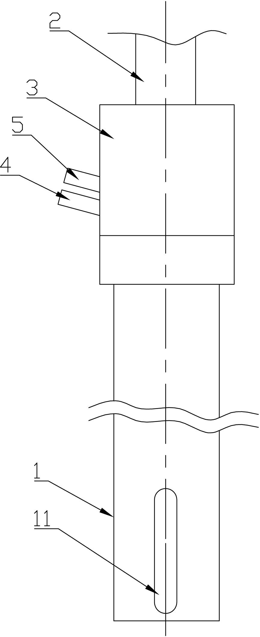
[0022] The application of the present invention in postoperative drainage will be described in detail below in conjunction with the accompanying drawings.

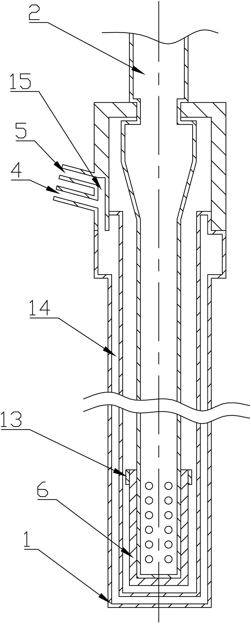
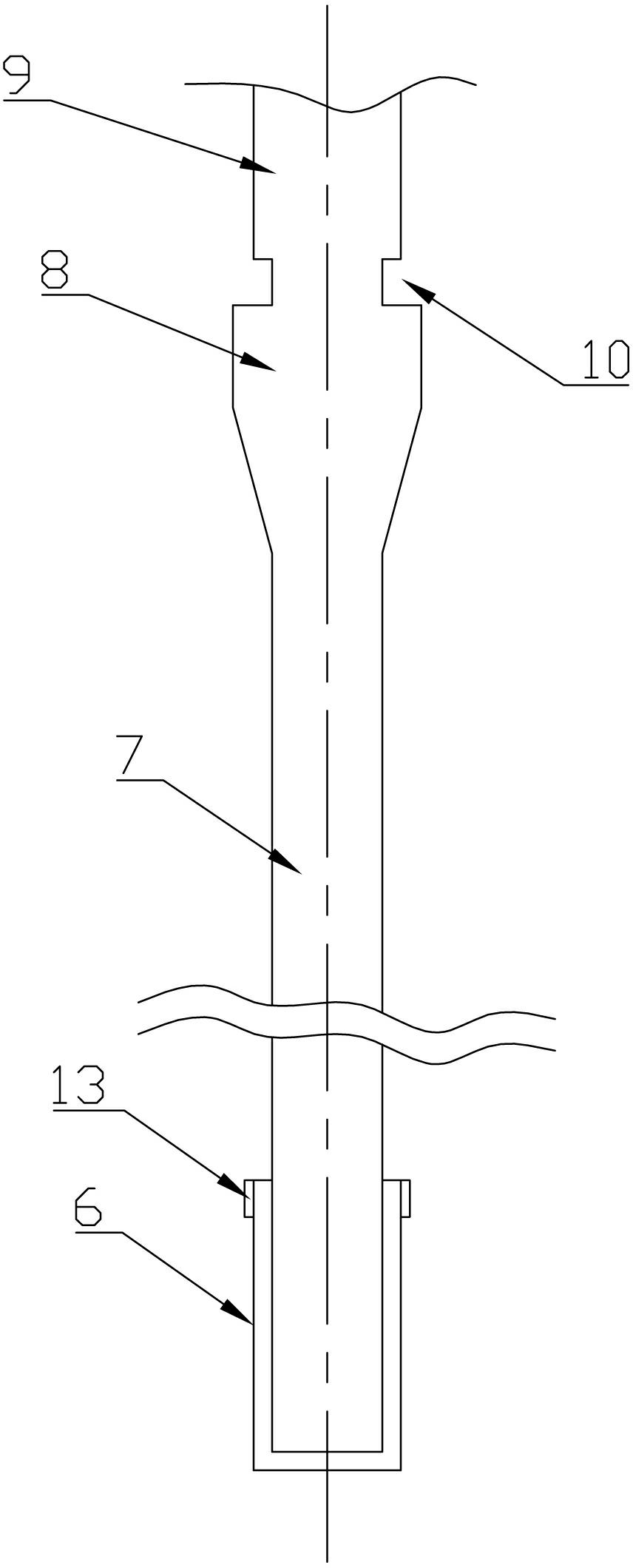
[0023] refer to Figure 1 to Figure 5 , a high negative pressure non-clogging drainage tube, comprising a built-in sleeve 1 with a plurality of sleeve drainage side holes 11 on the outer surface and a built-in drainage tube 2 with a plurality of inner tube drainage side holes on the outer surface, the built-in drainage tube 2. There is a built-in sleeve 1 outside the outer casing. The end surface of the built-in drainage tube 2 is provided with a drainage side hole of the inner tube, and a filter layer 6 is wrapped on the surface. 2 can be disassembled from the inner casing 1.

[0024] By setting the filter layer 6 on the built-in drainage tube 2 and the built-in drainage tube 2 can be replaced, then in the closed high negative pressure suction, the negative pressure is evenly distributed on the surface of the filter laye...


PUM


Abstract

The invention discloses a high negative pressure non-clogging drainage tube, which comprises an internal sleeve and an internal drainage tube; a plurality of sleeve drainage side holes are formed in the outer surface of the internal sleeve; a plurality of internal tube drainage slide holes are formed in the outer surface of the internal drainage tube; the internal sleeve is sleeved outside the internal drainage tube; the internal tube drainage holes are formed in the surface of the end part of the internal drainage tube, and the surface of the end part is covered with a filter layer; and the internal drainage tube can be detached from the interior of the internal sleeve. According to the invention, the filter layer is arranged on the internal drainage tube and the internal drainage tube can be changed, so that in suction in an enclosed high negative pressure environment, negative pressure is uniformly distributed on the surface of the filter layer through the filtration of the filter layer and the attenuated pressure to cause a to-be-drained object to enter a drainage bottle quickly, and the drainage tube is not easy to clog. The drainage tube, disclosed by the invention, is suitable for clinical medical treatment.

Description

technical field [0001] The invention relates to a medical device, in particular to a high negative pressure non-clogging drainage tube. Background technique [0002] External drainage refers to the mechanical measures to establish open channels between the human body cavity, organs, joints, tissues, etc. and the outside world, which is one of the basic operations of surgery. Existing surgical drainage tubes mainly include single-lumen drainage tubes and double-set drainage tubes. [0003] At present, the best drainage effect is cannula drainage, that is, there is a double-cannula drainage tube using the principle of low negative pressure or gravity drainage, including a built-in cannula placed in the patient's body cavity for cleaning, a built-in drainage tube for drainage, Dosing pot, dosing catheter and drainage external tube, the built-in sleeve is outside the built-in drainage tube, the front end of the built-in sleeve is open or not, the front end of the built-in drain...

Claims


Application Information

Patent Timeline
Patent Type & Authority Applications(China)
IPC IPC(8): A61M25/00A61M25/14
CPCA61M1/0023A61M1/008A61M2205/75A61M1/84A61M1/90
Inventor 朱新生
Owner 朱新生
Why Eureka
Try Eureka