Safe drum brake

A drum brake and safety technology, applied in the direction of mechanically driven drum brakes, brake actuators, etc., can solve the problems of large vehicle braking sliding distance and poor drum brake braking effect, so as to improve braking reliability and improve braking performance. Effect of stability, good braking stability

Inactive Publication Date: 2012-07-18
许志明 +1
View PDF4 Cites 8 Cited by
  • Summary
  • Abstract
  • Description
  • Claims
  • Application Information

AI Technical Summary

Problems solved by technology

[0003] The problem to be solved by the present invention is to provide a safety drum brake, which changes the working mode of the original drum brake which uses the cam to directly drive the expansion of the brake shoe, and effectively improves the shortcomings of the existing drum brake, such as poor braking effect and large vehicle braking sliding distance.

Method used


Image

  • Safe drum brake
  • Safe drum brake
  • Safe drum brake

Examples


Embodiment Construction

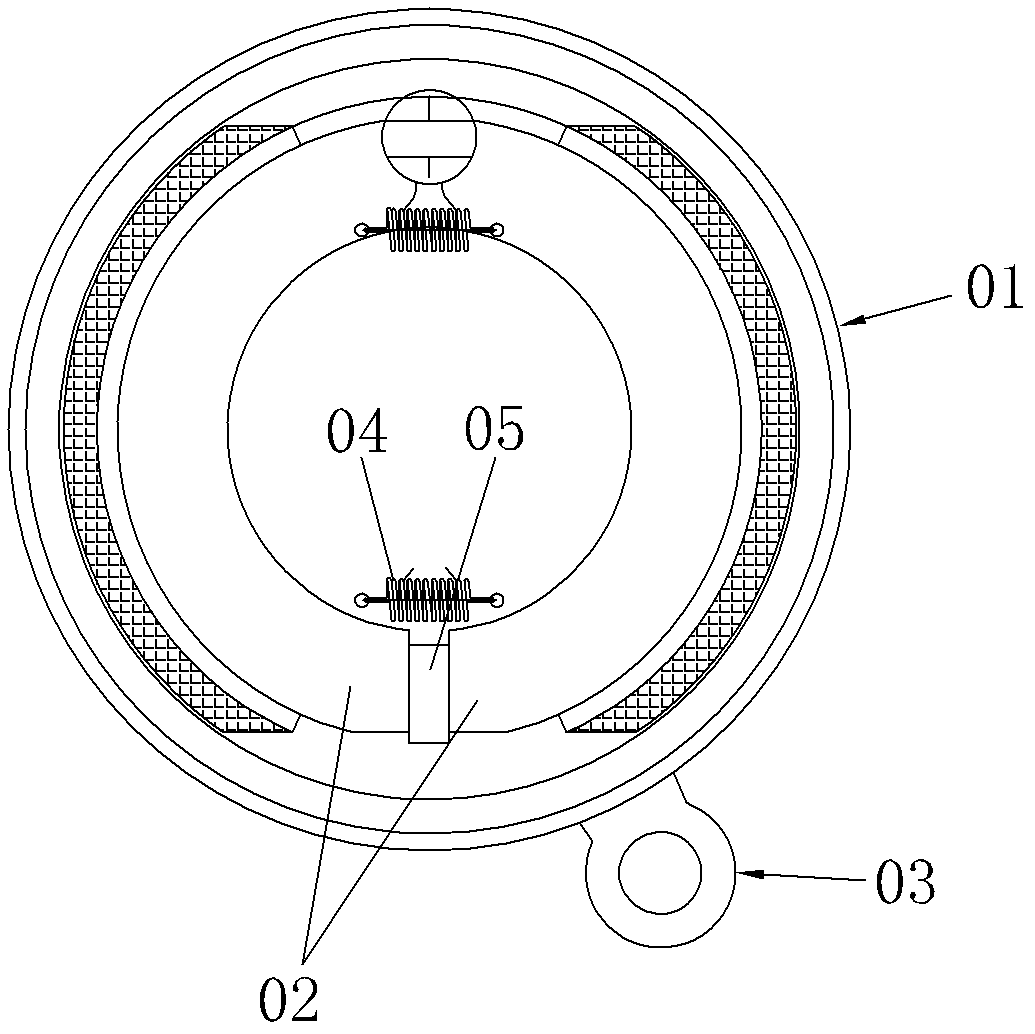
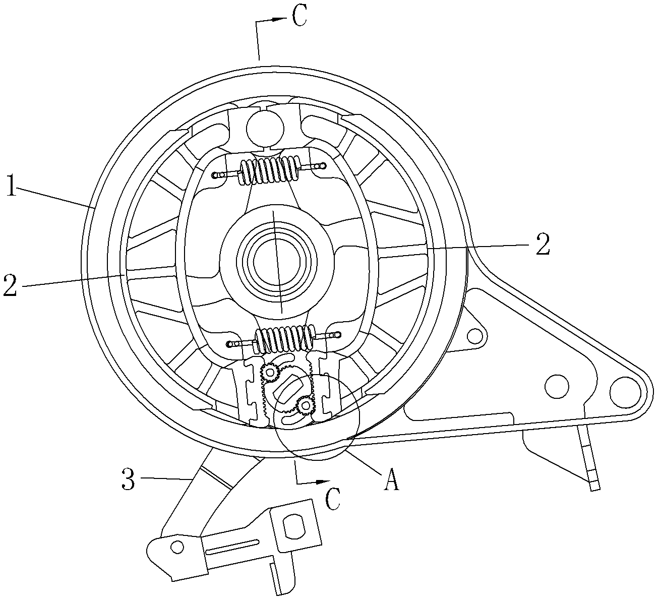
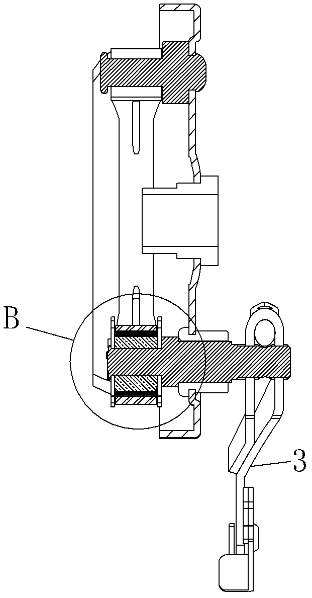
[0021] refer to Figure 2-4 , a safety drum brake, comprising a casing 1, a pair of brake shoes 2 and a brake arm assembly 3, one end of the brake shoe 2 is connected to the casing, and a gap between the other end of the brake shoe 2 and the brake arm The brake wheel 4 connected to the component 3, the roller 5 abuts between the brake wheel 4 and the brake shoe 2, also includes a positioning structure for the roller 5, the positioning structure includes a positioning plate 6, and the positioning plate 6 is provided with a limiting groove 61 , the roller 5 is provided with a protrusion embedded in the limiting groove 61. When the brake wheel 4 pushes the roller 5, the roller 5 always moves within the trajectory set by the limiting groove 61. The principle can refer to the applicant The previously applied patent number "2011203340168" and the invention patent named "a new type of drum brake" will not be described in detail here.

[0022] On the basis of the existing drum brake,...


PUM


Abstract

The invention discloses a safe drum brake which comprises a casing, a pair of brake shoes and a brake arm assembly, wherein one end of each of the brake shoes is rotatably connected on the casing, a brake wheel connected with the brake arm assembly is arranged between the gap of the other ends of the pair of the brake shoes, a pin roller is butted between the brake wheel and each of the brake shoes, and the pin roller is in tooth meshing with the brake shoes. As the roller is in tooth meshing with the brake shoes, the pin roller can be effectively prevented from slipping during braking, the braking reliability of the drum brake is improved, and simultaneously, the dislocation of the roller can be prevented, the stability of movement of the pin roller is improved, and the braking stability of the drum brake is further improved.

Description

technical field [0001] The invention relates to a drum brake. Background technique [0002] Drum brakes have been used in automobiles for nearly a century, but due to their reliability and powerful braking force, drum brakes are still used on many models today. Such as figure 1 As shown, most of the existing drum brakes are mainly composed of a housing 01, a pair of brake shoes 02, a brake cam 05, a brake rocker arm 03 and a reset part 04. When braking, the brake rocker arm drives the brake cam to rotate, and the brake cam forces the brake shoe 02 to expand and contact with the brake hub to generate friction to achieve braking. After braking, the reset component pulls the brake shoe 02 back to its original position. During the braking process, in addition to the wear between the brake shoe 02 and the brake hub, there will also be wear between the brake cam and the brake shoe, and the wear is always concentrated on several points or surfaces of the brake cam, which is extre...

Claims


Application Information

Patent Timeline
Patent Type & Authority Applications(China)
IPC IPC(8): F16D51/22F16D65/14
Inventor 许志明许文涛
Owner 许志明
Why Eureka
Try Eureka