Eureka AIR delivers breakthrough ideas for toughest innovation challenges, trusted by R&D personnel around the world.

Fastened round LED lamp

A technology of LED circular lamp and LED lamp board, which is applied in lighting and heating equipment, instruments, mechanical equipment, etc., can solve the problems of complicated production of rectangular lamp frame, low coupling efficiency, waste of light source, etc., so as to improve the utilization rate of light source. , The effect of improving the coupling efficiency and simplifying the connection structure

Inactive Publication Date: 2012-07-18
MAXRAY OPTICAL TECH FUJIAN
View PDF6 Cites 1 Cited by
  • Summary
  • Abstract
  • Description
  • Claims
  • Application Information

AI Technical Summary

Problems solved by technology

[0004] The starting position of the existing dots is close to the LED light source at the edge of the light guide plate, the light coupling efficiency is low, and there are many bright spots at the same time. As a result, the light scattered to these positions is not reflected, resulting in waste of light sources: Third, the ink on the surface of the LED light board is traditional green ink, which does not reflect, and absorbs light energy to reduce the brightness
[0005] The existing light frame structure is fastened by screws, which is low in work efficiency and high in cost
At the same time, the production of rectangular light frames is complicated, and it is not as efficient as the production of circular light frames.

Method used


Image

  • Fastened round LED lamp
  • Fastened round LED lamp
  • Fastened round LED lamp

Examples


Embodiment Construction

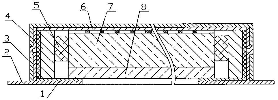
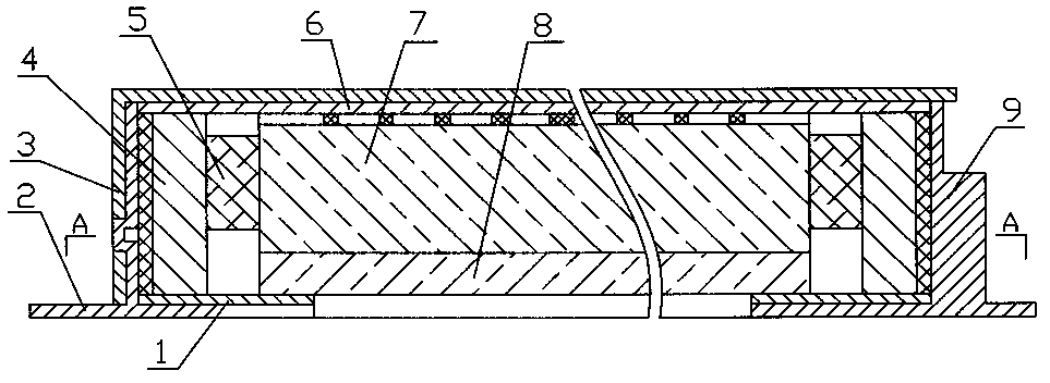
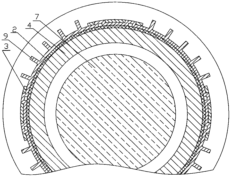
[0013] The structure of the first scheme of the present invention is: comprising a lamp frame 2, an LED lamp board 5, a top board 3, a top reflection layer, a light guide plate 7, a diffusion film 8, a circuit board 4, lead wires, and a power converter, and is characterized in that: Frame 2 is an annular body with an inverted "T" shape in cross-section. Several rectangular boss buckles are evenly distributed on the outer wall of the longitudinal ring plate around the annular body. The top plate 3 is in the shape of a barrel with the opening facing downward. A rectangular hole corresponding to the rectangular boss buckle of the lamp frame 2 is provided on the top; a corresponding circular disk-shaped reflective layer 1 is arranged on the plane of the inner circular disk plate at the bottom of the lamp frame 2, and the circular disk-shaped reflective layer 1 above the lamp frame 2 The inner wall of the longitudinal ring plate is bonded with a circuit board 4; the circuit board 4 ...


PUM


Abstract

A fastened round LED lamp comprises a lamp frame, an LED lamp panel, a top plate, a top reflecting layer, a light guide plate, a diffusion diaphragm, a circuit board, an outlet lead and a power converter. A plurality of rectangular boss fasteners are evenly distributed on the outer circumferential wall of the annular lamp frame with an inverted 'T'-shaped cross section, the upper plane of a round tube wall of the barrel-shaped top plate with an opening facing down is provided with rectangular holes corresponding to the rectangular boss fasteners, the rectangular holes and the rectangular boss fasteners are fixed in a fastened manner, a corresponding annular disc reflecting layer is arranged on an inner annular disc plate at the bottom of the lamp frame, the circuit board for inserting the LED lamp panel is adhered to the inner circumferential wall of a longitudinal annular plate above the reflecting layer of the lamp frame, white materials with high diffuse reflectivity are coated on the surface of a no-lamp-holder position of the LED lamp panel, or reflective sheets are adhered to the surface of a position except for a lamp holder of the LED lamp panel, the round diffusion diaphragm, the round light guide plate and the round top reflecting layer are sequentially arranged above a reflecting plate in an inner circle of the lamp panel, and the inner circle of the round tube wall of the top plate is sleeved on the outer wall of the longitudinal annular plate of the lamp frame by means of movable fit. The coated materials with the high diffuse reflectivity and the strip-shaped reflecting layers reflect light into the light guide plate, so that the utilization rate of a light source is increased.

Description

Technical field: [0001] The invention relates to an LED lamp, in particular to a buckle-type LED circular lamp. Background technique: [0002] Chinese patent 200920182700.1 discloses a "LED ceiling lamp". Its technical solution is: including a lamp frame, a lamp holder, a lamp, a lead wire, and a power converter. It is characterized in that the lamp frame is composed of a top plate and four horizontal U-shaped bars. , the four U-shaped strips are symmetrically distributed vertically and horizontally, and the lower surface of the upper horizontal strip is buckled on the upper surface of the square roof. After inserting the two connecting rods of two LED lamps into the corresponding jacks of the circuit board as the lamp holder, the printed circuit on the circuit board is fixedly connected with the end of the rods by soldering. The back of the circuit board is pasted and connected; the inner surface of the top plate of the light frame and the reflective film of the same area ...

Claims


Application Information

Patent Timeline
Patent Type & Authority Applications(China)
IPC IPC(8): F21S2/00F21V7/22F21V8/00F21V17/16F21Y101/02F21K9/238F21Y115/10
Inventor 陈志铭
Owner MAXRAY OPTICAL TECH FUJIAN
Why Eureka
Eureka Blog
Learn More