
Microwave drying equipment and dynamic microwave emission drying method thereof

A microwave drying and equipment technology, applied in drying, drying machine, lighting and heating equipment and other directions, can solve the problem of uneven microwave field, large drying equipment, and scattered textiles that cannot achieve good drying effect and other problems, to achieve the effect of uniform microwave field, small size and uniform energy distribution

Active Publication Date: 2015-01-07
李富旗
View PDF8 Cites 0 Cited by
  • Summary
  • Abstract
  • Description
  • Claims
  • Application Information

AI Technical Summary

Problems solved by technology

[0003] The purpose of the present invention is to overcome the large volume of drying equipment in the prior art, the drying process is non-dynamic drying, the microwave field is uneven, and it cannot achieve a good drying effect on dispersed textiles.

Method used


Image

  • Microwave drying equipment and dynamic microwave emission drying method thereof
  • Microwave drying equipment and dynamic microwave emission drying method thereof
  • Microwave drying equipment and dynamic microwave emission drying method thereof

Examples


Embodiment Construction

[0027] The present invention will be further described below in conjunction with accompanying drawing and specific embodiment:

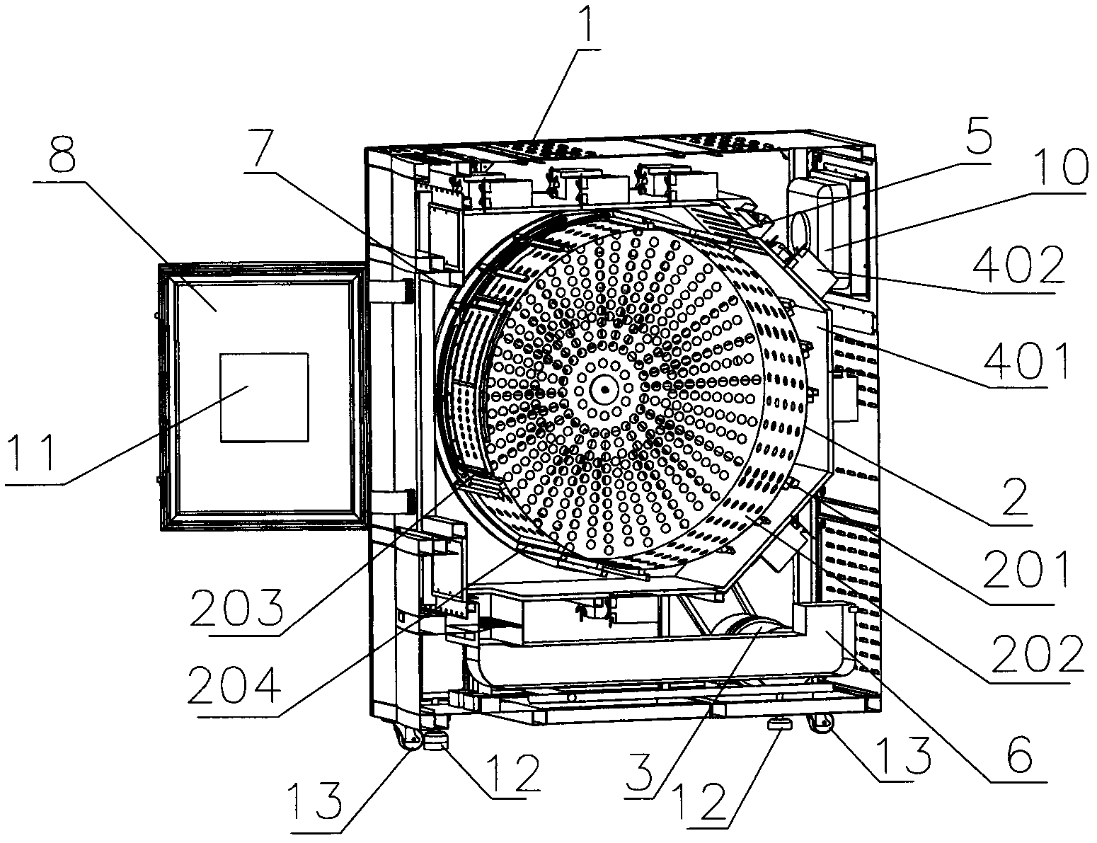
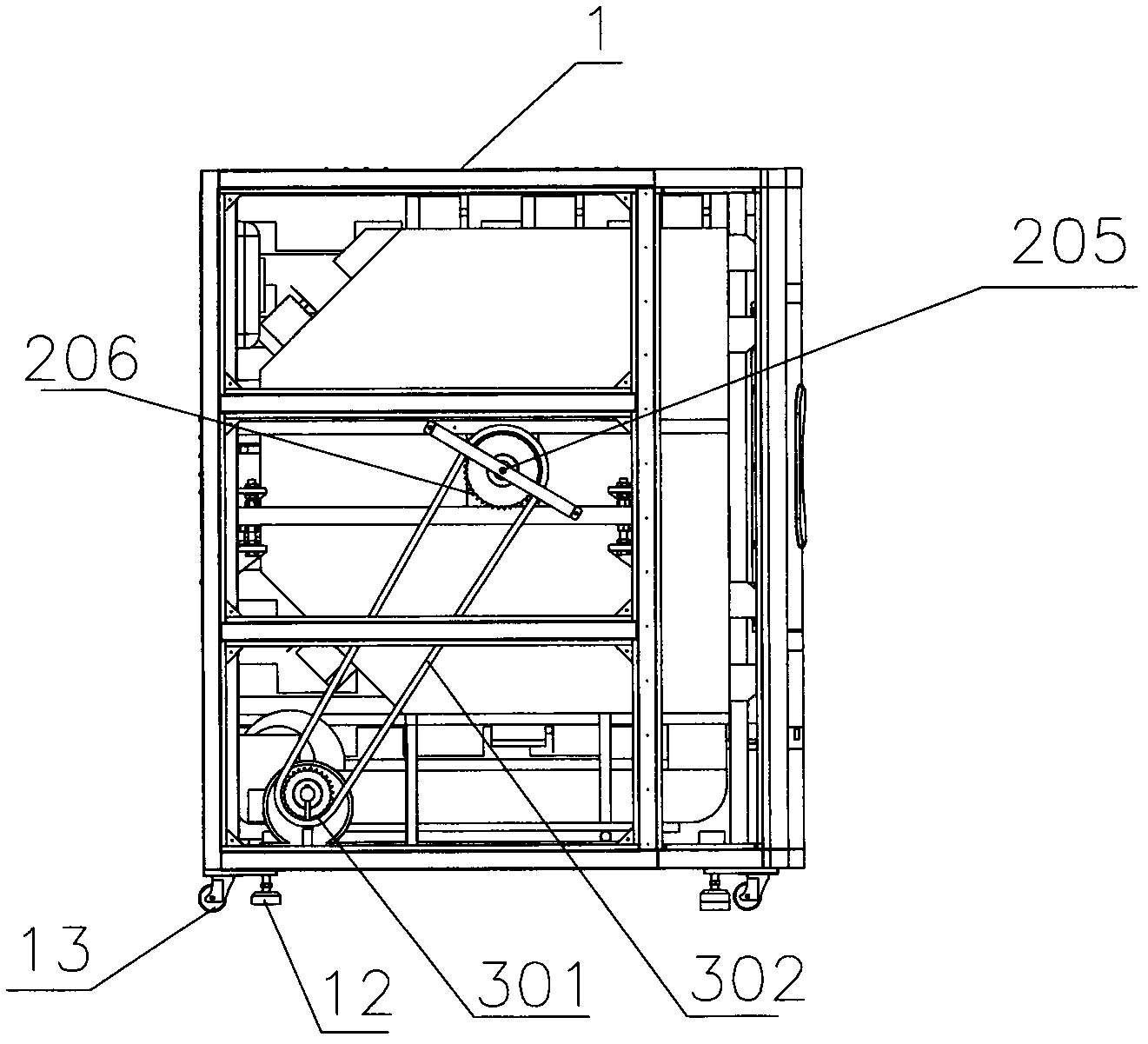
[0028] refer to figure 1 As shown, the microwave drying equipment disclosed in the invention includes a cabinet 1 , a drum 2 , a driving device 3 and a magnetron installation cavity 4 .

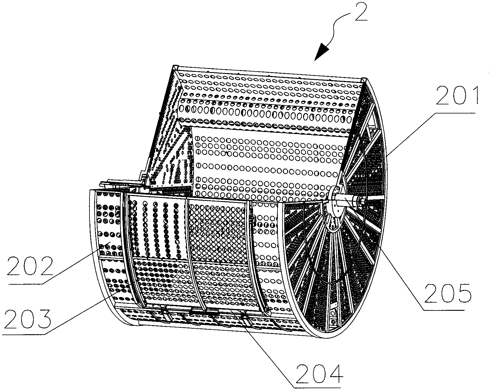
[0029] refer to image 3 As shown, the drum 2 includes a cylindrical drum frame 201 and a load net 202; the cylindrical surface of the drum frame 201 is provided with a feeding and retrieving opening 203, and the drum 2 is provided with a sliding door 204, and the feeding and retrieving Both sides of mouth 203 are respectively provided with a track, and the both sides of described sliding sliding door 204 are respectively provided with a pulley, and the pulleys on both sides of described sliding sliding door 204 are installed on the track of described feeding and taking material opening 203 both sides; The carrying net 202 is installed on the side and two bottom s...


PUM


Abstract

The invention provides microwave drying equipment and a dynamic microwave emission drying method of the microwave drying equipment. The microwave drying equipment comprises a cabinet, a roller and a driving device as well as a magnetron installation cavity body, wherein the roller comprises a cannular frame and a bearing network, the outer surface of a magnetron installing panel is provided with magnetrons, and the magnetrons are arranged on a waveguide and are arranged on the magnetron installation cavity body through the waveguide; according to the method, fabric is put in the roller, after the equipment is started, the roller rotates in a back and forth manner, the microwave transmits in a dynamic loop manner, and all the magnetrons on the magnetron installing panel are divided into a plurality of magnetron groups; and each magnetron group is composed one or more magnetrons which are selected from the magnetron installing panel which is in the shape of a five-surface polygon. When the microwave drying equipment is operated, the magnetron groups are in dynamic loop, so that one group or more than one group of magnetrons can be simultaneously started. With the adoption of the microwave drying equipment with the structure, the fabric is in a dynamic microwave field, so that the fabric is uniformly dried, and the drying efficiency is greatly improved, and the aim of saving energy is achieved..

Description

【Technical field】 [0001] The invention relates to drying equipment and a drying method thereof, in particular to a microwave drying equipment and a dynamic microwave emission drying method thereof. 【Background technique】 [0002] At present, the equipment used for drying in industry is generally the traditional drying method of electric heating or steam heating and gas heating air to dry objects. It belongs to an indirect drying object. The drying efficiency is low, the energy consumption is large, the drying time is long and the drying is uneven. Steam drying, due to the use of boilers and coal-fired, is also very polluting. Microwave drying is a method of using electromagnetic waves to directly act on the water molecules of the object to be dried, which is energy-saving, clean and efficient. The microwave drying equipment is generally a tunnel drying equipment, and its microwave head is installed on the upper part of the tunnel cavity. However, the tunnel-type drying e...

Claims


Application Information

Patent Timeline
Patent Type & Authority Patents(China)
IPC IPC(8): F26B11/02F26B21/00F26B25/00F26B7/00
Inventor 李富旗
Owner 李富旗
Learn More