
Rail straining and sensing method based on bidirectional strain matching fiber grating demodulating technique

A fiber grating demodulation and fiber grating technology, which is applied in the direction of using optical devices, measuring devices, instruments, etc., can solve the problems of influence and the influence cannot be well eliminated, and achieve the effect of high sensitivity, simple structure and fast speed.

Inactive Publication Date: 2012-07-18
SOUTHWEST JIAOTONG UNIV
View PDF2 Cites 22 Cited by
  • Summary
  • Abstract
  • Description
  • Claims
  • Application Information

AI Technical Summary

Problems solved by technology

At present, common solutions include matching grating demodulation method and using filtering and differential methods to process data to eliminate the influence of temperature and noise, etc. However, the influence of temperature on strain measurement cannot be well eliminated sometimes after using these methods
In the traditional matching demodulation method, one of the gratings is generally installed on the track, and the other is placed beside the track or in the demodulation unit. This method is not a big problem at room temperature or relatively low ambient temperature, because the ambient temperature When the rail temperature is low, the difference between the temperature of the rail and the ambient temperature is small or basically the same, but when the ambient temperature rises to a certain level (such as a hot summer day), the rail temperature is generally about 20°C higher than the ambient temperature, and the temperature must be right at this time. The traditional matching grating strain measurement results have a great influence; and when the temperature fluctuation of the rail is large, the methods of processing data such as filtering and differentiation cannot achieve good results
Therefore, in these cases, the above-mentioned method still has some deficiencies in the use of high-speed railways.

Method used


Image

  • Rail straining and sensing method based on bidirectional strain matching fiber grating demodulating technique
  • Rail straining and sensing method based on bidirectional strain matching fiber grating demodulating technique
  • Rail straining and sensing method based on bidirectional strain matching fiber grating demodulating technique

Examples


Embodiment Construction

[0022] The present invention will be further described below in conjunction with the accompanying drawings.

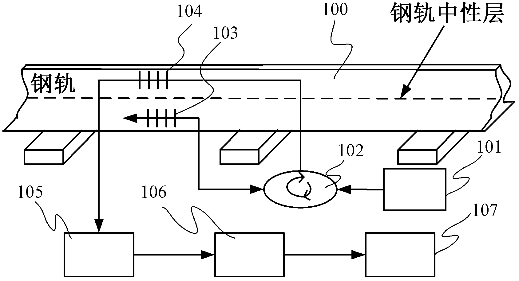
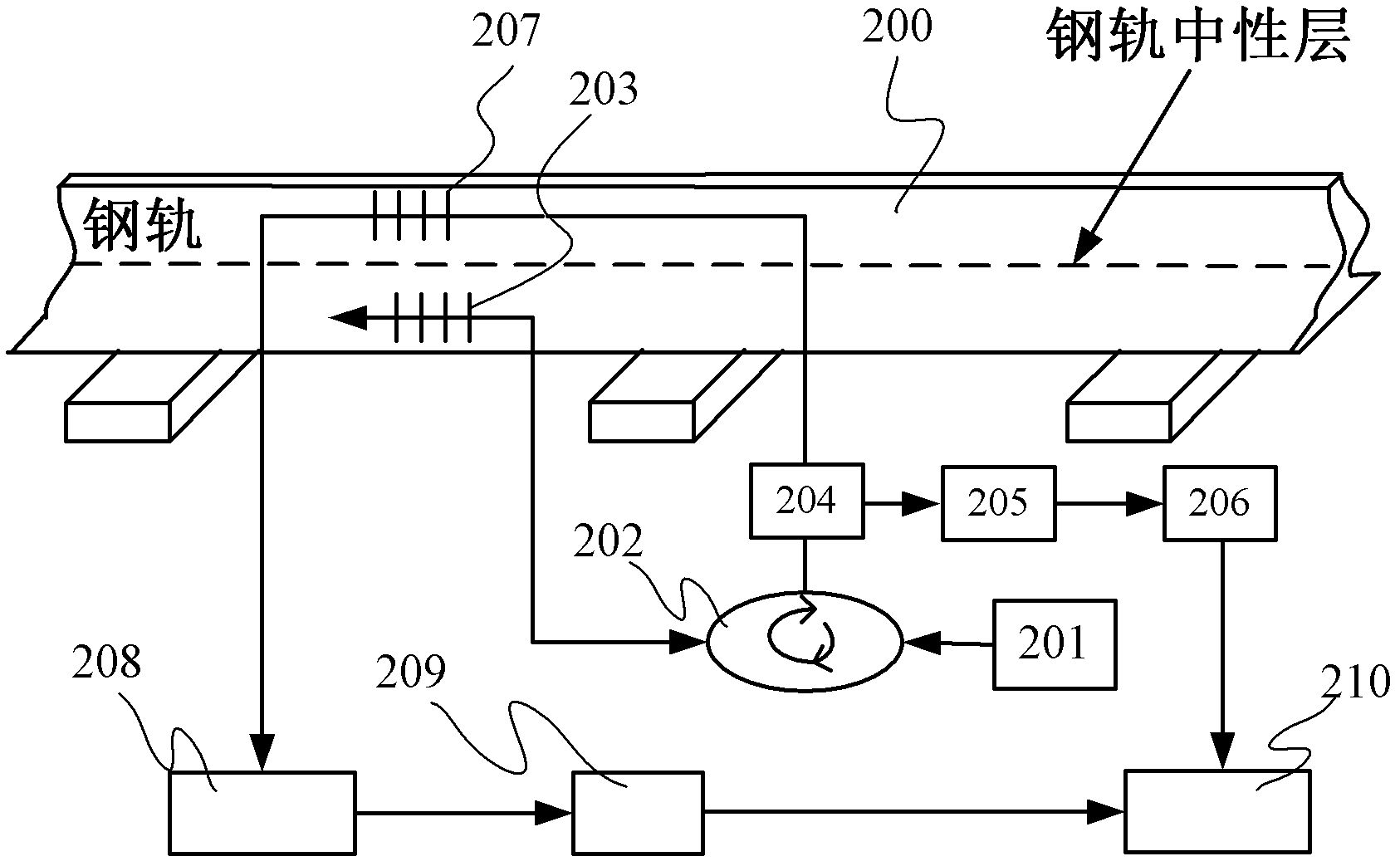
[0023] figure 1 It is a schematic diagram of the structure principle of the entire sensing system adopted when the present invention is implemented. The broadband light source (101) emits a light beam, which can be an ASE or SLED laser. Its typical bandwidth is tens of nanometers, and the reflection spectrum width of the fiber grating sensor is generally 0.2 nm ~ 0.3nm, so in conventional FBG sensing applications, it can be considered that the light source spectrum is much larger than the FBG reflection spectrum bandwidth. The light beam emitted by the light source enters the first sensing grating FBG1 (103) through the circulator 102, and the sensing grating FBG1 (103) reflects the light beam back to a narrow-band light, which is used as signal light and enters the second sensor grating through the circulator 102 A sensing grating FBG2 (104), enters the photodetector...


PUM


Abstract

The invention discloses a rail straining and sensing method based on bidirectional strain matching fiber grating demodulating technique. The method can be used for monitoring the quantity of shafts, the weight of the wheels or the positions of trains in running as well as the single-point or multi-point strain distributing conditions of the track. Compared with the traditional matching fiber grating demodulating technique, the method is different in that two matching gratings are respectively arranged on the side surfaces which are close to the top and the bottom of a rail in the system; according to the bidirectional strain (pulling strain and pressing strain) acted on the two gratings, the monitoring sensitivity can be improved, and the problem of the cross sensitivity of the strain temperature of the fiber grating during measuring the rail strain can be effectively solved. The method is simple in structure and fast to sample. The method is also be suited to monitor the dynamic strain of the rail.

Description

Technical field: [0001] The invention relates to the field of fact monitoring equipment manufacturing for high-speed railways and ordinary railway systems, in particular to a method based on optical fiber sensing technology to realize the perception of the strain state of the track, and obtain the number of axles, wheel weight, position and railway track safety of the running train through analysis and processing. state and other information technology Background technique: [0002] In the operation of railway lines, the monitoring of track strain is of great significance. By monitoring the strain of the rail under the load of the train, the safety monitoring of the weight measurement, axle counting, positioning and track status of the train can be realized. Traditional strain measurement methods (such as using resistance strain gauges, electromagnetic wires, etc.) are susceptible to electromagnetic interference and have poor stability, while fiber grating strain sensors hav...

Claims


Application Information

Patent Timeline
IPC IPC(8): G01B11/16
Inventor 闫连山周威张志勇潘炜罗斌邹喜华赵明杰
Owner SOUTHWEST JIAOTONG UNIV
Learn More