Distributed optical fiber sensing device and method based on phase demodulation

A distributed optical fiber, sensing device technology, applied in the direction of mitigating undesired effects, changing/correcting change laws, etc., to achieve the effects of large bandwidth, improved signal-to-noise ratio, and large dynamic range

Active Publication Date: 2014-09-24
杭州安远科技有限公司
View PDF8 Cites 0 Cited by
  • Summary
  • Abstract
  • Description
  • Claims
  • Application Information

AI Technical Summary

Problems solved by technology

However, the traditional Φ-OTDR technology approximates the optical phase change directly through the light intensity, which is easily affected by the fluctuation of the light intensity itself and the laser intensity noise (Relative Intensity noise, RIN)

Method used


Image

  • Distributed optical fiber sensing device and method based on phase demodulation
  • Distributed optical fiber sensing device and method based on phase demodulation
  • Distributed optical fiber sensing device and method based on phase demodulation

Examples


Embodiment 1

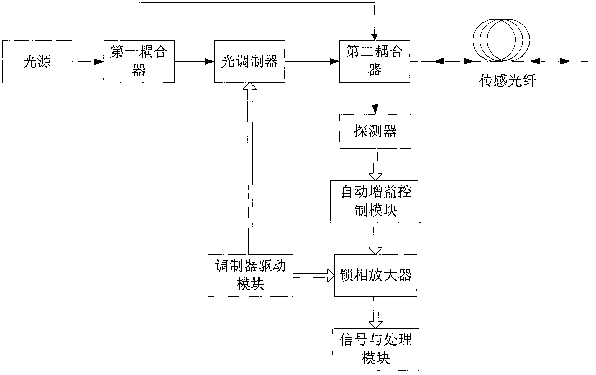
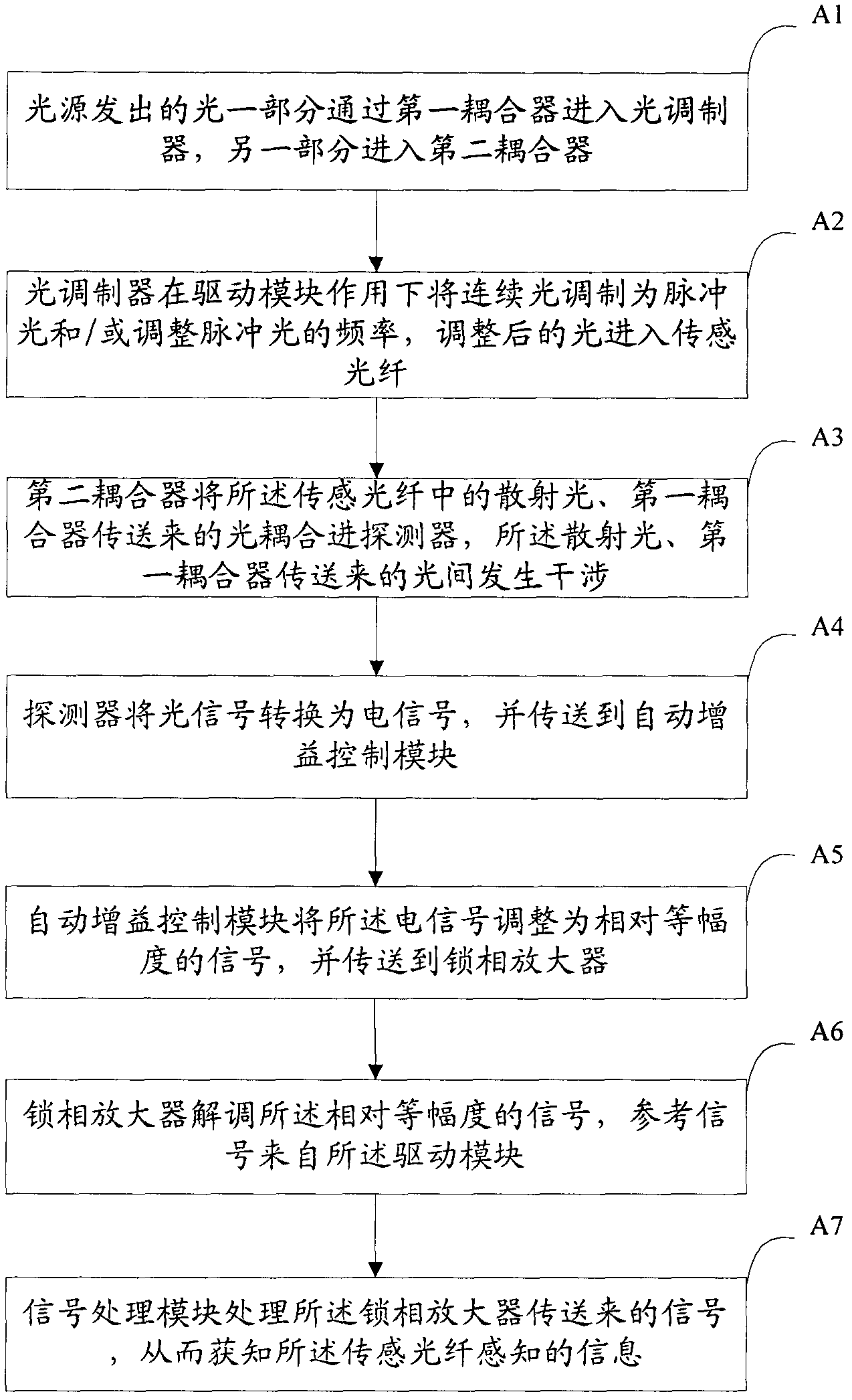
[0047] figure 1 The basic structural diagram of the distributed optical fiber sensing device based on phase demodulation according to the embodiment of the present invention is schematically given, as shown in figure 1 As shown, the sensing device includes a light source and a sensing fiber connected in sequence; the light source can be a laser, such as a continuous semiconductor laser with a narrow linewidth; the sensing device further includes:

[0048] a first coupler, the first coupler is used to couple the light emitted by the light source into the light modulator and the second coupler respectively;

[0049] An optical modulator, the optical modulator is used to adjust the continuous light into pulsed light and / or adjust the frequency of the light, and the adjusted light enters the sensing fiber; preferably, the optical modulator is an acousto-optic modulator.

[0050] A drive module, the output end of the drive module is respectively connected to the optical modulator ...

Embodiment 2

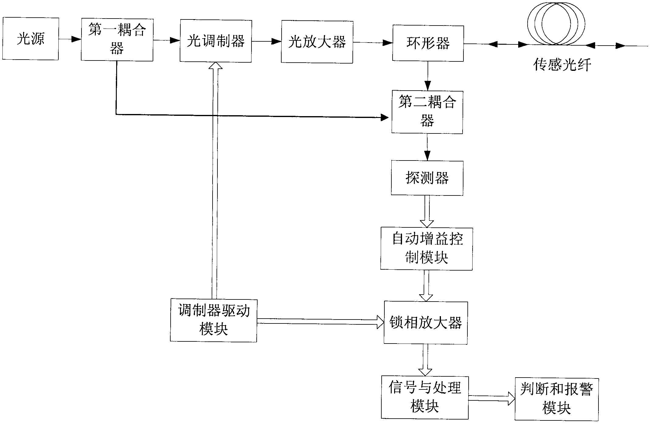
[0070] image 3 The basic structural diagram of the distributed optical fiber sensing device for simultaneous measurement of vibration according to the embodiment of the present invention is schematically given, as image 3 Shown, different from embodiment 1 is:

[0071] 1. An optical amplifier and a circulator are sequentially connected downstream of the optical modulator, and the circulator transmits the output light of the optical amplifier to the sensing fiber, and transmits the Rayleigh scattered light in the sensing fiber to the second coupler;

[0072] 2. The sensing device further includes a judgment module and an alarm module:

[0073] Judging module, the judging module judges whether the parameter sent by the signal processing module exceeds the threshold; the judging module can be implemented by circuit or software, and the specific implementation method is the existing technology in the field, so it will not be repeated here.

[0074] An alarm module, when the j...

Embodiment 3

[0079] The distributed optical fiber sensing device based on phase demodulation is different from Embodiment 2 in that a pulsed light source, such as a semiconductor laser with a narrow linewidth, is used, and an optical modulator is used to adjust the frequency of the pulsed light.


PUM


Abstract

The invention discloses a super large dynamic range distributed optical fiber sensing device and method based on phase demodulation. The super large dynamic range distributed optical fiber sensing device comprises a light source, a coupler, an acoustic optical modulator, an optical amplifier, a circulator, a detector, an automatic gain control device, a modulator driving device, a phase-locking amplifier, a sensing optical cable and a signal processing and signal outputting device. The automatic gain control device is adopted in the invention, large dynamic range signal detection can be realized; a phase demodulating detection device of the phase-locked amplifier is adopted, influence of intensity noise is reduced, and high flexibility high bandwidth vibration signal detection can be realized, thus large dynamic range distributed vibration sensing can be realized. The super large dynamic range distributed optical fiber sensing device disclosed by the invention has the beneficial effect that long-distance distributed sensing with the following advantages can be realized: dynamic range is large, locating accuracy is high, interference sensing sensitivity is high, bandwidth used for detecting a vibration signal is wide, multipoint location can be realized, and detection distance is long.

Description

technical field [0001] The invention relates to the field of optical fiber sensing and safety protection, in particular to a distributed optical fiber sensing device and method based on phase demodulation and super large dynamic range. Background technique [0002] In 1993, Φ-OTDR (Phase sensitive Opitcal Time Domain Reflector) technology was invented by Professor Taylor of American Agricultural and Mechanical University (US5194847). Since its invention, this technology has attracted the attention of distributed sensing researchers and companies from all over the world. Φ-OTDR technology indirectly realizes the detection of intrusion signals through the detection intensity. [0003] For Φ-OTDR technology, if the long-distance distributed sensing of 80Km is to be realized, the detection circuit needs to have a dynamic range of 32dB in total based on the loss calculation of 0.2dB / Km. If the detection distance is longer, a larger dynamic range is required. This places very h...

Claims


Application Information

Patent Timeline
Patent Type & Authority Patents(China)
IPC IPC(8): G01D3/028G01D3/024
Inventor 毛慧
Owner 杭州安远科技有限公司
Why Eureka
Try Eureka