
Focal length measuring method of auto-collimating differential confocal lens

A technology of differential confocal and measurement method, applied in the direction of testing optical performance, etc., can solve the problems of large error and inability to achieve, and achieve the effect of improving the precision of fixed focus and the sensitivity of fixed focus

Active Publication Date: 2014-01-08
BEIJING INSTITUTE OF TECHNOLOGYGY
View PDF8 Cites 0 Cited by
  • Summary
  • Abstract
  • Description
  • Claims
  • Application Information

AI Technical Summary

Problems solved by technology

However, the lens vertex focal length and focal length measurement methods proposed in the above documents are only suitable for measuring ultra-long focal lengths. If they are used for the measurement of general focal lengths and shorter focal lengths, the error will be large or it will not be possible.

Method used


Image

  • Focal length measuring method of auto-collimating differential confocal lens
  • Focal length measuring method of auto-collimating differential confocal lens
  • Focal length measuring method of auto-collimating differential confocal lens

Examples


Embodiment 1

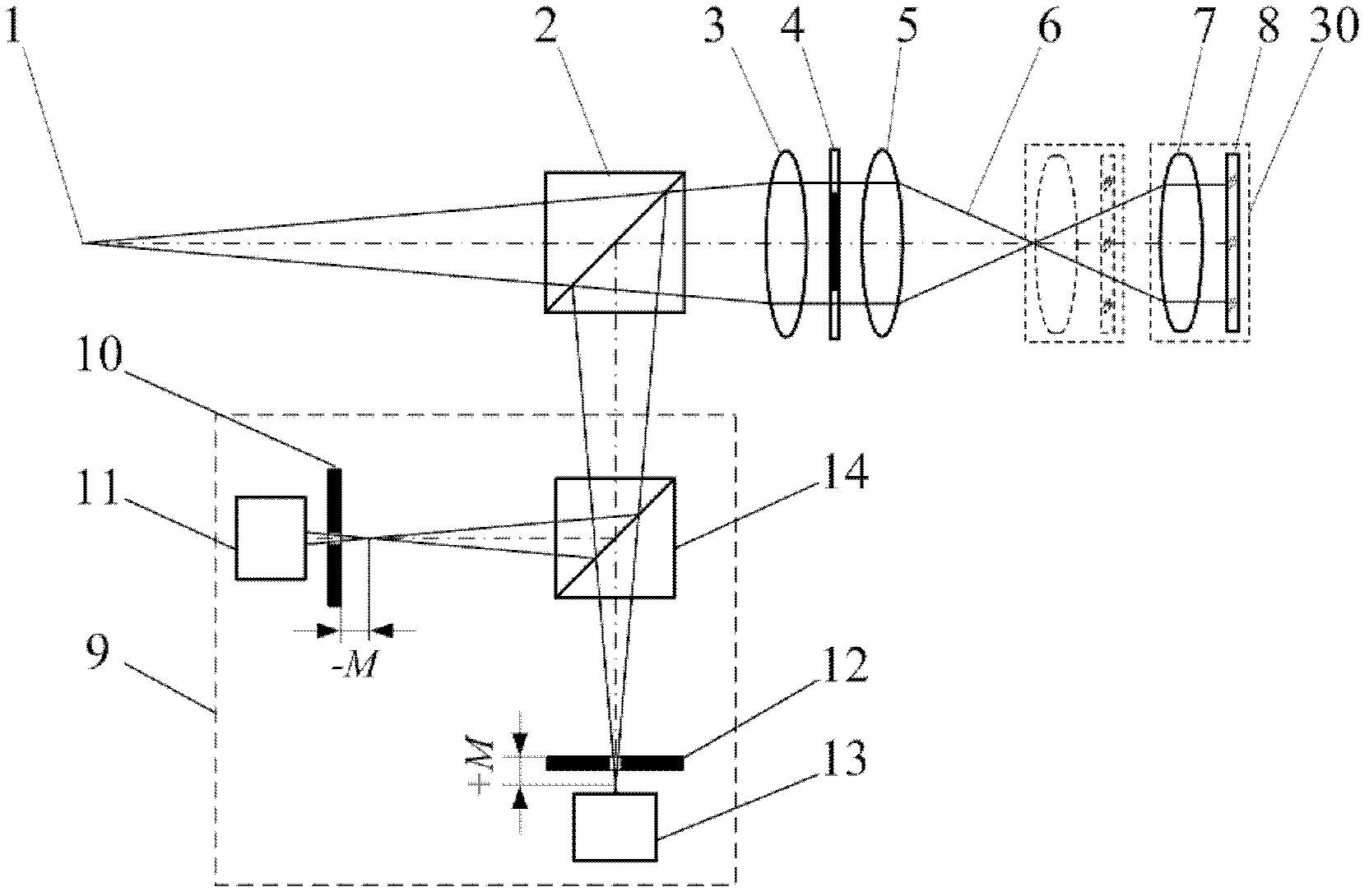
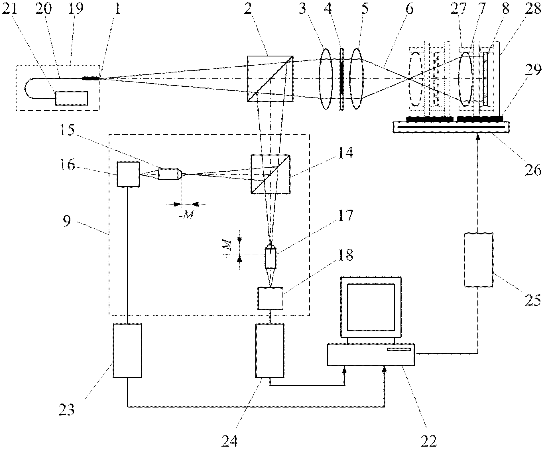
[0038] When the measured lens 7 has a diameter of D=25.4mm and a radius of curvature of the front surface r 1 =90.1mm, the radius of curvature of the back surface r 2 =-115.4mm, material is K9 glass, thickness b=4mm, nominal focal length and vertex focal length are f′99mm, l F ′=97.5mm convex lens, the focal length measurement device of the self-collimation differential confocal lens such as figure 2 As shown, the measurement steps are:

[0039] (a) Start the measurement software in the main control computer 22, turn on the laser 21, and the light emitted by the laser 21 is transmitted through the optical fiber 20 to form the point light source 1. The light emitted by the point light source 1 forms a parallel beam after passing through the beam splitter 2 and the collimating lens 3, and the parallel beam is converged by the converging lens 5 to form a measuring beam 6;

[0040] (b) The measured lens 7 is placed on the four-dimensional adjustment frame 27, the auxiliary pla...

Embodiment 2

[0047] According to the radius of curvature r of the front surface of the measured lens 7 1 =90.1mm, the radius of curvature of the back surface r 2 =-115.4mm, refractive index n=1.5163, thickness b=4mm, and the top focal length l of the lens measured in Example 1 F '=97.5276mm, the focal length of the measured lens 7 can be measured indirectly:

[0048] f ′ = l F ′ + r 2 b n ( r 2 - r 1 ) + ( n - 1 ) b = 99.0176 ...


PUM


Abstract

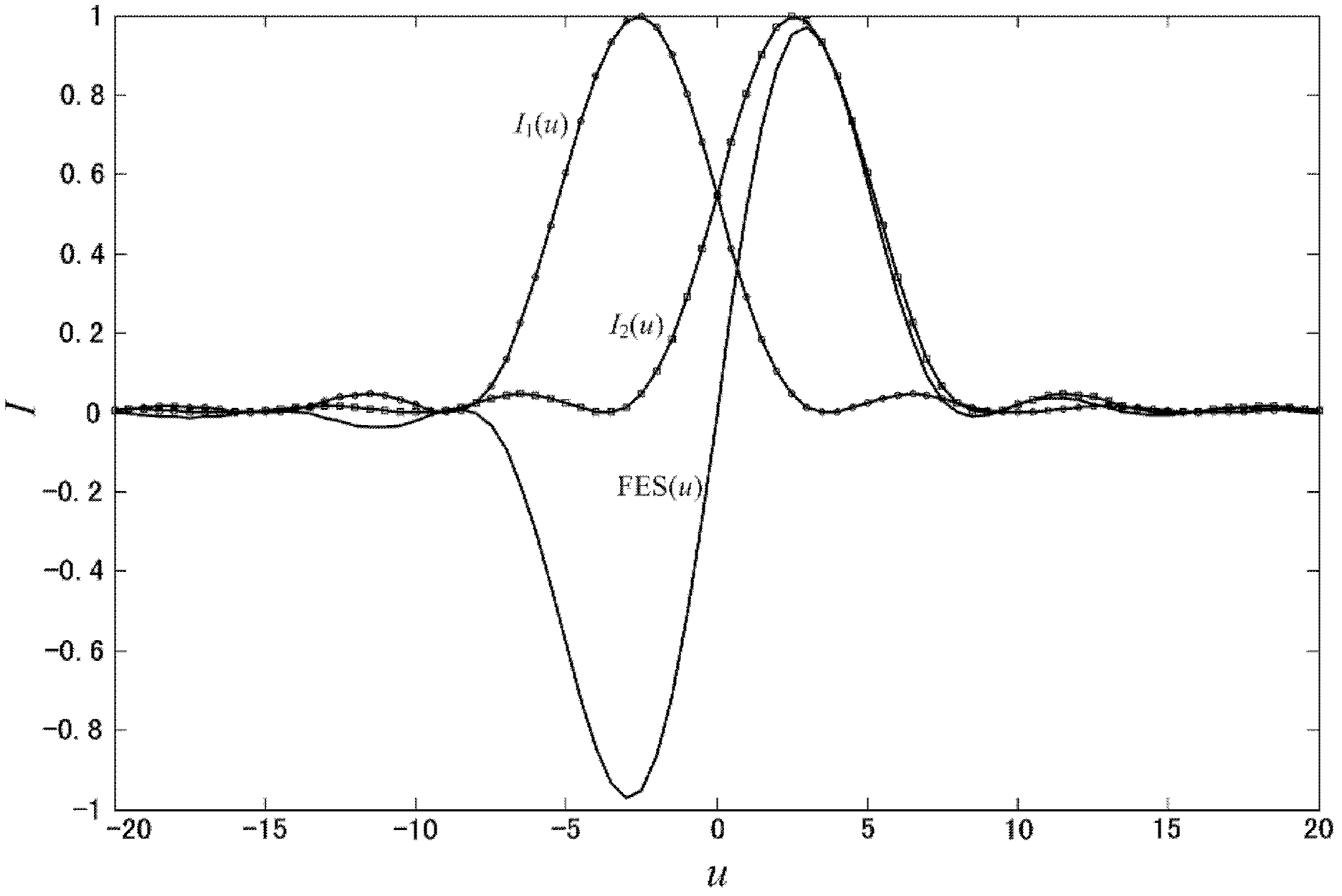
The invention relates to a focal length measuring method of an auto-collimating differential confocal lens, belonging to the technical field of optical precision measurement. The method blends the auto-collimating thought into the differential confocal measuring method, and the high-accuracy measurement of lens vortex focal length and focal length is further realized. The method has the core thought of introducing an auxiliary plane reflecting mirror to collimate the measured lens into parallel light beams to be reflected along the original light path, the differential confocal technology is matched to accurately position the focal point and the surface vertex of the tested lens, and the vertex focal length and the focal length of the measured lens are obtained. In the invention, the auto-collimating measurement thought is fused into the differential confocal measurement method for the first time, and the positions of the focal length and the surface vertex of the measured lens are accurately determined by using the zero crossing point of the differential confocal response curve. The focal length measuring method has the advantages of high measurement accuracy, strong anti-environment disturbance ability and the like and can be used for the high-accuracy detection of lens focal length.

Description

technical field [0001] The invention belongs to the technical field of optical precision measurement and can be used for the detection of the focal length of a lens and the high-precision focal length measurement in the assembly process of an optical system. technical background [0002] Focal length measurement is an ancient and classic topic of lens parameter measurement, and its importance is self-evident. The focal length is one of the most important parameters among the many parameters of the lens. For lens design, it is nothing more than adjusting various parameters to ensure that the focal length of the lens meets the design requirements and the imaging performance meets the system requirements. Lens focal length measurement usually includes vertex focal length measurement and focal length measurement. In the process of system design and adjustment, these two parameters are usually inseparable, so it is required to measure the vertex focal length and focal length of t...

Claims


Application Information

Patent Timeline
Patent Type & Authority Patents(China)
IPC IPC(8): G01M11/02
Inventor 邱丽荣杨佳苗赵维谦吴华玲李佳
Owner BEIJING INSTITUTE OF TECHNOLOGYGY
Learn More