
Transient fluorescence lifetime measurement method and measurement system based on single photon counting

A technology of single-photon counting and fluorescence lifetime, which is applied in the fields of fluorescence/phosphorescence, material excitation analysis, etc., can solve the problems of reduction, difficult acquisition time, and difficulty in measuring the ultra-fast process of transient change of fluorescence lifetime, achieving high measurement accuracy, High signal-to-noise ratio, suppression of interference from background noise and thermal noise

Inactive Publication Date: 2012-07-18
INST OF PHYSICS - CHINESE ACAD OF SCI
View PDF6 Cites 41 Cited by
  • Summary
  • Abstract
  • Description
  • Claims
  • Application Information

AI Technical Summary

Problems solved by technology

[0011] However, due to the limitations of the signal acquisition dead time of the electronic system and the minimum signal storage time, it is difficult to further reduce the acquisition time of each fluorescence decay kinetic curve. Therefore, the existing TCSPC fluorescence It is difficult for the lifetime measurement system to increase the interval of the time series to the resolution of the nanosecond level, that is, it is difficult to measure the ultrafast process of the transient change of the fluorescence lifetime

Method used

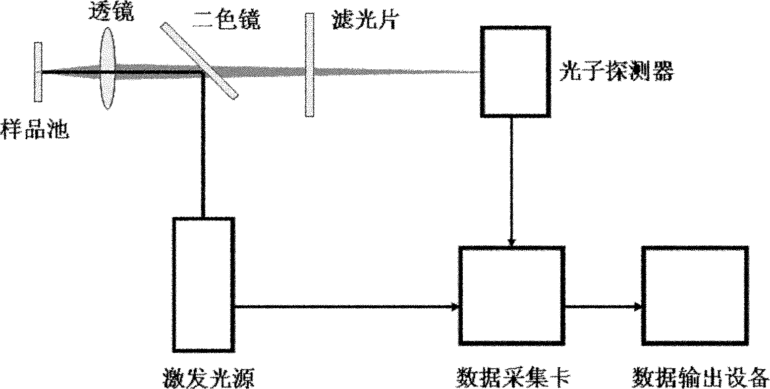
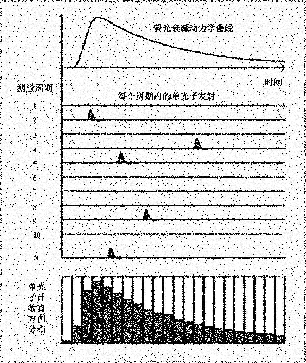
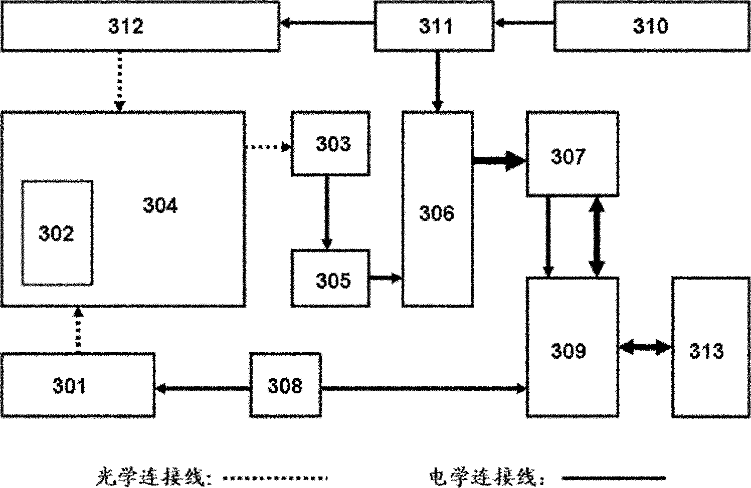

Image

  • Transient fluorescence lifetime measurement method and measurement system based on single photon counting
  • Transient fluorescence lifetime measurement method and measurement system based on single photon counting
  • Transient fluorescence lifetime measurement method and measurement system based on single photon counting

Examples


Embodiment Construction

[0064] Below, the present invention will be further described in conjunction with the accompanying drawings and embodiments.

[0065] According to one embodiment of the present invention, a method for measuring transient fluorescence lifetime based on single photon counting is provided, comprising the following steps 1) to 5):

[0066] 1) The sample is irradiated with pulsed light at a high repetition rate to excite fluorescence.

[0067] 2) Induce a transient change in the fluorescence lifetime of the sample according to a certain period. The transient change satisfies the following: when the trigger arrives, the sample fluorescence lifetime begins to undergo a transient change. After a period of time, the sample characteristics and fluorescence lifetime undergo a recovery process. In the next Before the trigger arrives, the sample characteristics and fluorescence characteristics return to the original state. For relevant content, please refer to the literature: Ye, M.P., et...


PUM


Abstract

The invention provides a transient fluorescence lifetime measurement method based on single photon counting, which includes the following steps that: 1) a sample is irradiated by pulse light with high recurrence frequency to excite fluorescence; 2) the fluorescence lifetime of the sample is induced to have transient changes according to a certain period; 3) the fluorescence photons of the sample are detected and the corresponding high-speed digital pulse signals which represent the single photon signals are outputted; 4) the macro times of the photons are divided into different time zones, the photons are allocated to different groups according to the macro time and the groups correspond to the time zones of the macro time of the photons; and 5) time-relevant single photon counting is conducted on the photons in each macro time zone according to the high-speed digital pulse signals so as to get a fluorescence decay curve of the fluorescence photons in the macro time zone relative to time. In such way, the fluorescence decay curves in different macro time zones can be obtained. The invention further provides a corresponding transient fluorescence lifetime measurement system. The transient fluorescence lifetime measurement method and system are capable of recording the transient fluorescence decay dynamic curves of the nanosecond time sequence.

Description

technical field [0001] The present invention relates to the technical field of fluorescence lifetime measurement, in particular, the present invention relates to a transient fluorescence lifetime measurement method and a corresponding measurement system Background technique [0002] Measuring the fluorescence lifetime of labeled and unlabeled fluorophores is one of the important means to study the structure, physical and chemical properties of biological systems. For example, by measuring the fluorescence lifetime of labeled and unlabeled fluorophores, information on the status of tissue metabolism, changes in protein or DNA structures, and interactions between molecules can be obtained. Moreover, imaging with high spatial resolution can also be achieved through the measurement of fluorescence lifetime. It can be seen that the measurement of fluorescence lifetime is one of the important technical means in the field of biophotonics. [0003] Time-correlated single photon co...

Claims


Application Information

Patent Timeline
IPC IPC(8): G01N21/64
Inventor 黄晓淳李得勇翁羽翔
Owner INST OF PHYSICS - CHINESE ACAD OF SCI
Learn More