
Wiring structure for partial discharge test of balance traction transformer

A traction transformer, partial discharge technology, applied in the direction of testing dielectric strength, measuring device casing, etc., can solve problems that cannot be directly applied

Inactive Publication Date: 2012-07-18
TIANWEI YUNNAN TRANSFORMER
View PDF4 Cites 9 Cited by
  • Summary
  • Abstract
  • Description
  • Claims
  • Application Information

AI Technical Summary

Problems solved by technology

[0005] The balanced traction transformer is a 110kV class insulation product, which is a special transformer for electrified railways. According to the standard requirements, a short-term induced voltage withstand test (routine test) and a long-term induced voltage test (special test) with partial discharge measurement should be carried out. Due to its internal structure, especially the arrangement of lead wires and windings, which is different from ordinary power transformers, the conventional partial discharge test method cannot be directly applied, and another test method must be used to meet the test requirements

Method used


Image

  • Wiring structure for partial discharge test of balance traction transformer
  • Wiring structure for partial discharge test of balance traction transformer
  • Wiring structure for partial discharge test of balance traction transformer

Examples


Embodiment Construction

[0017] The balanced traction transformer is a special transformer used in the electrified railway traction power supply system. The balanced traction transformer can change the three-phase power system into a two-phase power system with two phases with equal amplitude and a phase difference of 90 electrical degrees. The transformer has the advantages of high capacity utilization, low harmonic content and low fluctuation loss, and its impact on the power supply system is the smallest in the traction transformer series.

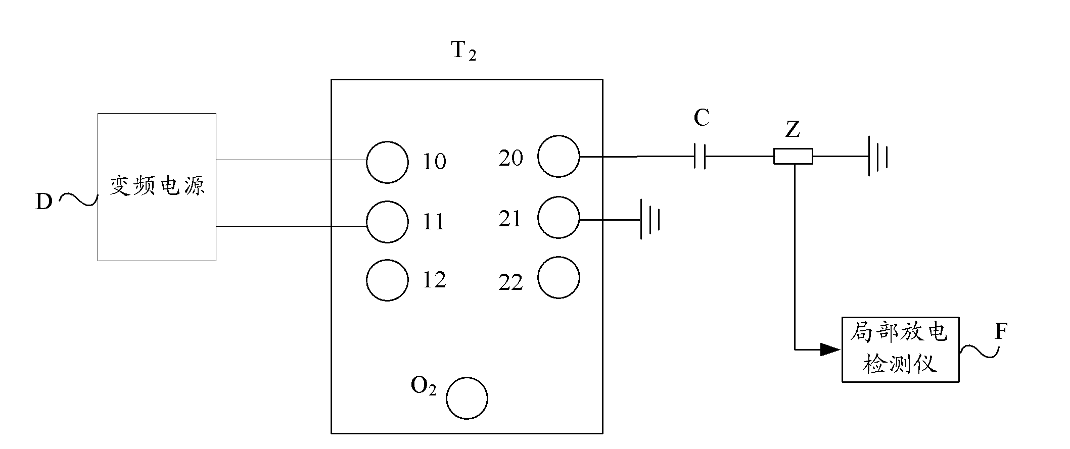
[0018] figure 1 It is a schematic diagram of the wiring structure of the balanced traction transformer partial discharge test in the embodiment of the present invention, as figure 1 As shown, the wiring structure includes a variable frequency power supply D and a partial discharge detector F.

[0019] Wherein, the frequency conversion power supply D and the tested balanced traction transformer T 2 The low-voltage side of which the two-phase winding terminals ...


PUM


Abstract

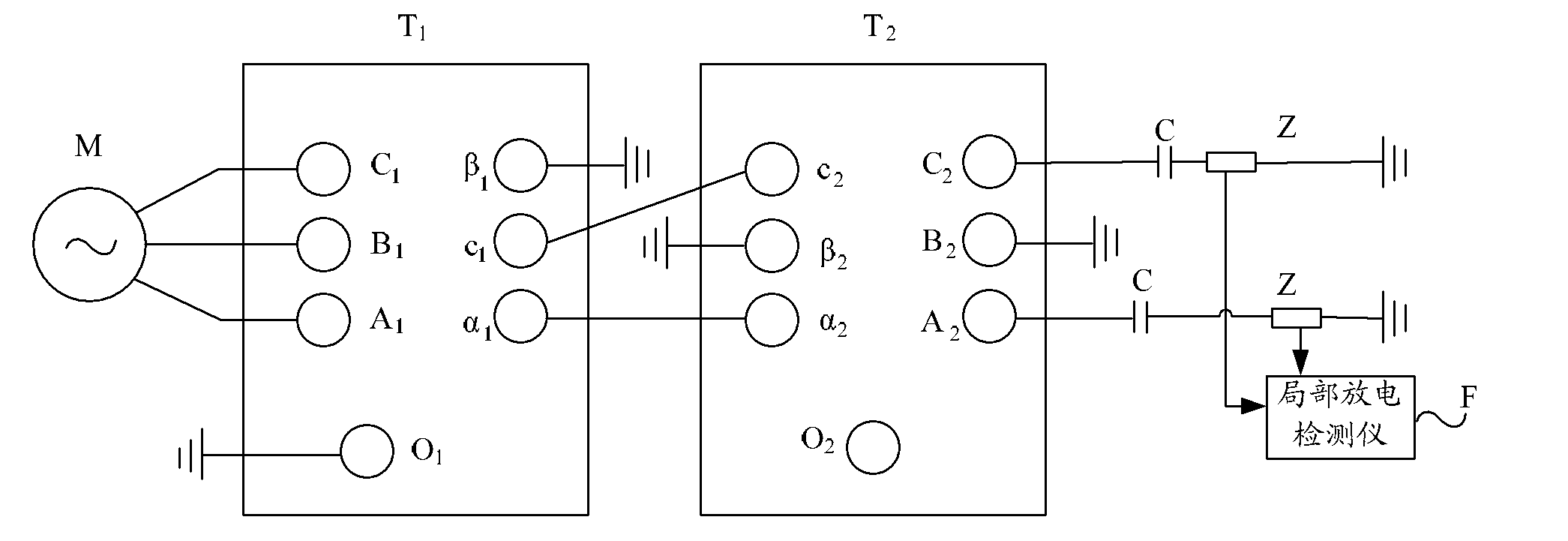
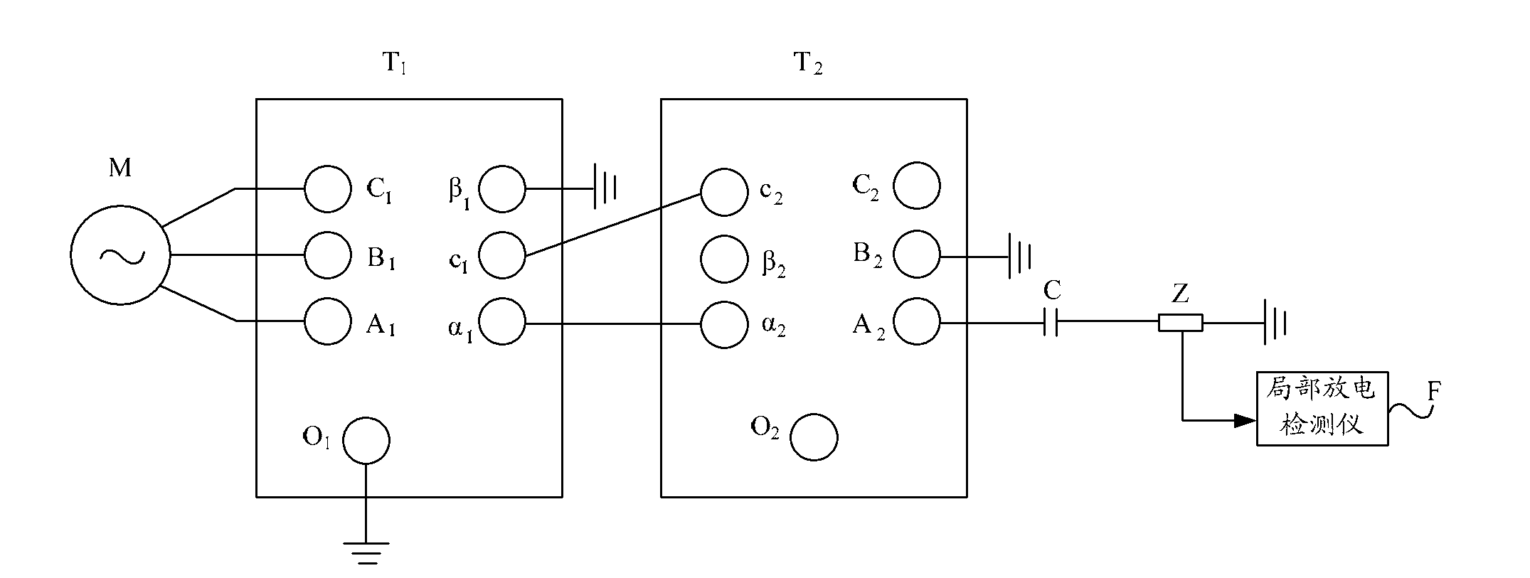
The invention provides a wiring structure of a partial discharge test of a balance traction transformer. The wiring structure comprises a variable frequency power supply and a partial discharge detector, wherein the variable frequency power supply is connected with wiring terminals of two windings at a low-voltage side of the tested balance traction transformer; a neutral point of the tested balance traction transformer is supported; wiring terminals of one non-tested phase or two phases of windings at a high-voltage side of the tested balance traction transformer are grounded; a wiring terminal of the tested-phase winding at the high-voltage side of the tested balance traction transformer is grounded through a coupling capacitor and a detection impedor; and the signal output end of the detection impedor is connected with a partial discharge detector. Due to the adoption of the wiring structure, the partial discharge test for the balance traction transformer can be carried out and apparent discharge of the tested phase of the balance traction transformer is measured, so that whether the tested phase meets the insulating requirement or not is judged and the requirement of the balance traction transformer on the partial discharge test is met.

Description

technical field [0001] The invention relates to transformer test technology, in particular to a wiring structure for partial discharge test of a balanced traction transformer. Background technique [0002] When the field strength generated by the applied voltage in the electrical equipment is sufficient to discharge the insulating part of the area, but this discharge phenomenon does not form a fixed discharge channel in the discharge area, it is called partial discharge. [0003] During the long-term operation of the transformer, some weak parts of its internal insulation will undergo partial discharge under the action of high field strength, which will lead to a decrease in insulation performance. Under the long-term action of severe partial discharge, it will even cause the breakdown of the transformer. Therefore, It affects the safe and reliable operation of transformers, especially ultra-high voltage transformers, under long-term working voltage. [0004] In order to en...

Claims


Application Information

Patent Timeline
Patent Type & Authority Applications(China)
IPC IPC(8): G01R1/04G01R31/12
Inventor 杨绍斌赵太明叶剑云赵燕芳
Owner TIANWEI YUNNAN TRANSFORMER
Learn More