
Single-phase intelligent energy meter distributed correction method

A smart electric energy meter, distributed technology, applied in the direction of measuring electric variables, measuring devices, instruments, etc., can solve the problems of incomplete synchronization of time, poor consistency of electric energy meters, large accidental errors in calculating meter calibration parameters, etc., to achieve accuracy and The effect of improving consistency, saving installation time, and improving work efficiency

Active Publication Date: 2012-07-18
北方智能装备有限公司
View PDF5 Cites 26 Cited by
  • Summary
  • Abstract
  • Description
  • Claims
  • Application Information

AI Technical Summary

Problems solved by technology

[0018] The total time spent by the existing smart energy meter calibration method is usually more than 20 minutes, including manual operations such as installation and removal of the energy meter. The calibration time of each meter is about 35 minutes, and the 48-meter meter calibration station is used for 8 hours to calibrate the meter658 block smart energy meter
Moreover, in the prior art, when the power source usually fluctuates due to grid interference, the electric energy collected by the standard meter and the pulse output of each electric energy meter are not completely synchronized due to time. At this time, the accidental error in calculating the meter calibration parameters will become larger, resulting in the same batch of electric energy meters. Poor performance, there is a problem that some electric energy meters are out of tolerance
Before calibrating the meter, it is necessary to connect the pulse output terminal of each watt-hour meter to be calibrated to detect the output error of the watt-hour meter. Not only is the speed slow, but workers are also prone to errors in operation.

Method used

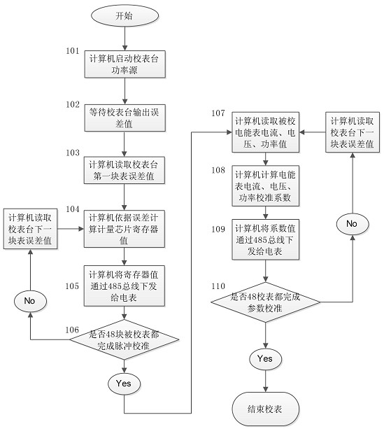
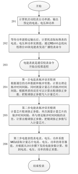
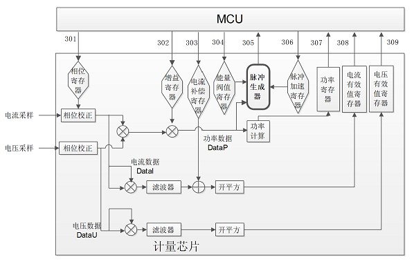

Image

  • Single-phase intelligent energy meter distributed correction method
  • Single-phase intelligent energy meter distributed correction method
  • Single-phase intelligent energy meter distributed correction method

Examples


Embodiment Construction

[0033] The following takes the calibration of the national grid single-phase smart energy meter as an example, combined with image 3 The distributed calibration method is further explained.

[0034] The basic current calibration 1.0 phase error calibration steps of the FireWire channel are as follows:

[0035] Step 1, the main control computer controls the power source of the meter calibration station to output rated voltage, rated current, and 1.0 phase through the RS232 bus; the main control computer reads the current voltage, current, and power values ​​from the standard electric energy meter, and broadcasts In this way, a 1.0 phase error calibration command is issued through the RS485 bus. The main control computer enters the timing waiting state, and the following steps are completed by the MCU of each electric energy meter;

[0036]Step 2, pulse acceleration: All the watt-hour meters to be calibrated receive the command to start meter calibration at the same time, rea...


PUM


Abstract

The invention provides a single-phase intelligent energy meter distributed correction method, and relates to a correction method for energy meters. The invention realizes the distributed correction method by utilizing software and hardware resources of intelligent energy meters, each correction point is only required to be communicated with a corrected energy meter once, and the specific pulse acceleration technique in the intelligent energy meters is used; a master control computer is not required to acquire the pulse input of each energy meter, and a high-precision crystal oscillator inside the energy meter is used as a clock reference during the error detection, so that the output pulse interval of a metering chip can be accurately caught; through the correction of rough adjustment and fine adjustment, the error of each correction point is within plus or minus 0.1%, and the correction precision and consistency are remarkably improved; and an error detection line is not required to be connected in the correction process, so that the time for mounting each energy meter is saved, and the labor intensity is lowered.

Description

technical field [0001] The invention relates to a meter calibration method of an electric meter, in particular to a distributed meter calibration method of a single-phase intelligent electric energy meter. Background technique [0002] In recent years, my country's smart grid construction has been in full swing, and single-phase smart meters have been widely used across the country. In 2011, the total amount of bidding by the State Grid Corporation alone reached 76,008,800 smart meters. Faced with such a huge order quantity, many manufacturers have problems such as untimely supply and out-of-tolerance errors of individual electric energy meters. The calibration of smart electric energy meters is an important link in the production of intelligent electric energy meters that is related to production efficiency and product quality. [0003] At present, the calibration of existing smart energy meters adopts a centralized control method with the main control computer as the core,...

Claims


Application Information

Patent Timeline
Patent Type & Authority Applications(China)
IPC IPC(8): G01R35/04
Inventor 高新王占元张俊哲宋延林
Owner 北方智能装备有限公司
Learn More