
Voltage stabilizing switching circuit for power supply

A switching circuit, power supply voltage regulation technology, applied in the direction of electronic switches, electrical components, adjusting electrical variables, etc., can solve the problems of reducing the magnetic core, increasing the complexity of the process, no cost, etc., to improve the voltage regulation rate and reduce the cost. , The effect of improving the voltage regulation rate

Inactive Publication Date: 2012-07-18
HUIZHOU SANHUA IND
View PDF6 Cites 5 Cited by
  • Summary
  • Abstract
  • Description
  • Claims
  • Application Information

AI Technical Summary

Problems solved by technology

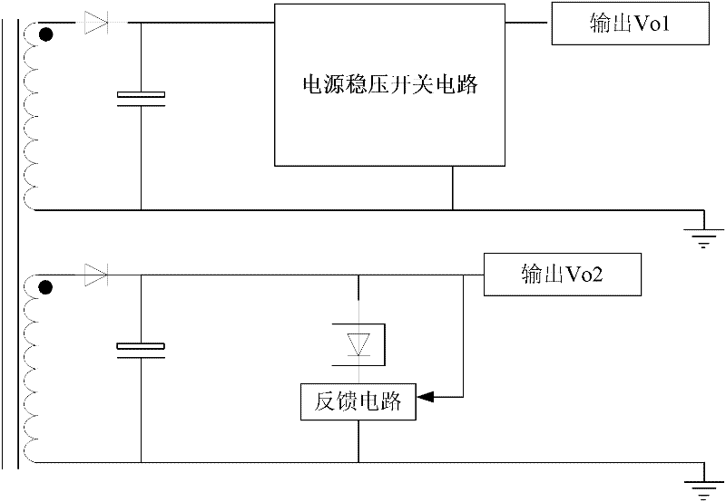
[0003] However, the current multi-output power supply with ON / OFF electronic switch is only designed as an ON / OFF function during design, that is, it only plays a simple on-off role. In actual multi-output applications There is a very obvious deficiency: it has no stabilizing effect on the output voltage of the power supply circuit.
[0007] 2.1. Reduce the GAP length of the center column of the magnetic core, such as the flyback power supply, its disadvantage is that the output power of the power supply is limited;
[0008] 2.2. The disadvantage of adopting low-leakage inductance transformer technology is that it increases the complexity of the process and increases the cost of the transformer;
[0009] 2.3. The disadvantage of using a larger transformer is that it increases the cost of the transformer;
[0010] 3. The disadvantage of adopting the transformer technology that improves the adjustment rate is that the complexity of the process increases and the cost of the transformer increases;
[0011] It can be seen that there is no low cost and high voltage regulation power supply voltage regulation switching circuit in the prior art.

Method used


Image

  • Voltage stabilizing switching circuit for power supply
  • Voltage stabilizing switching circuit for power supply
  • Voltage stabilizing switching circuit for power supply

Examples


Embodiment Construction

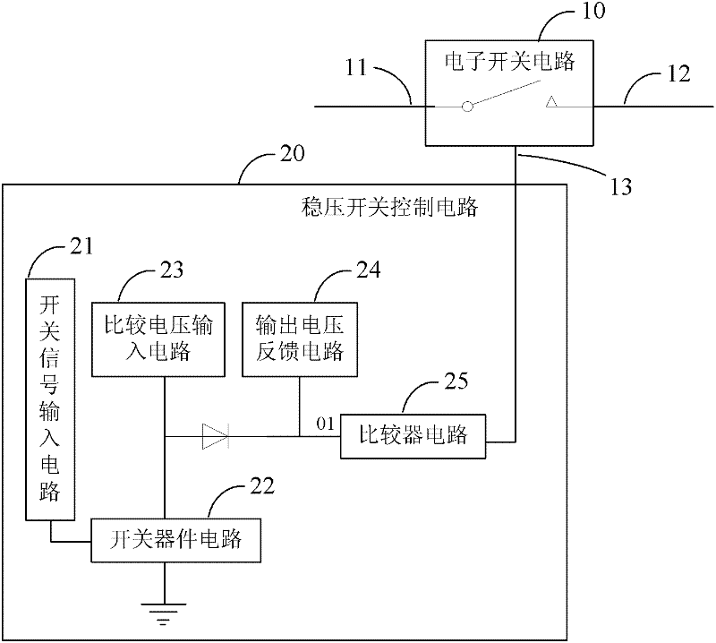
[0021] see figure 1 , figure 1 It is a structural schematic diagram of the power supply voltage stabilizing switch circuit of the present invention.

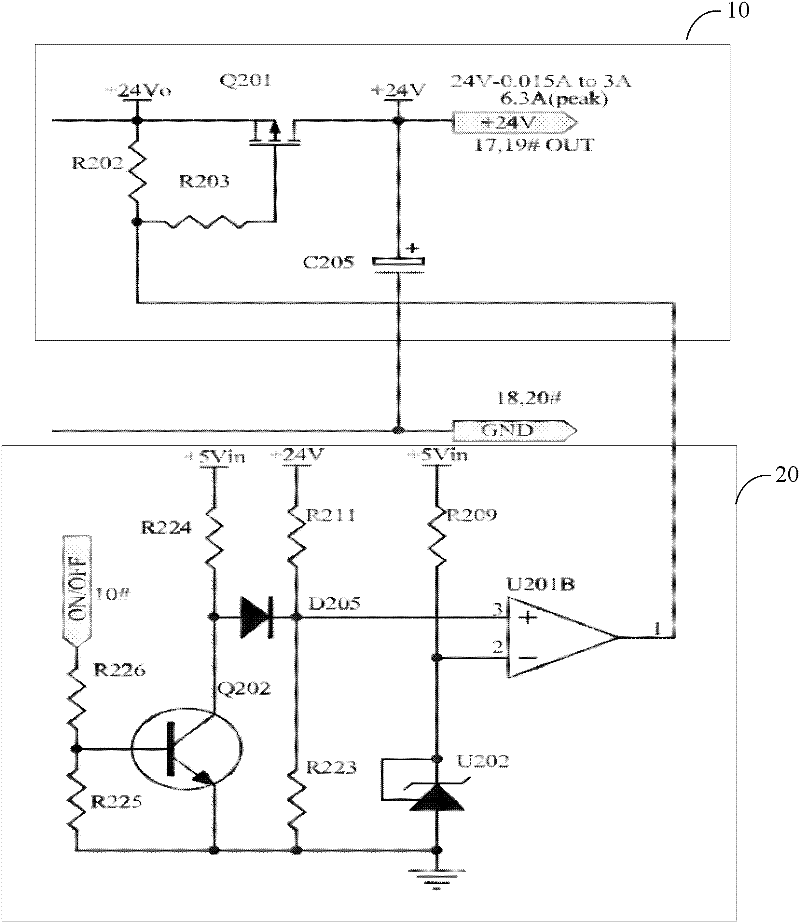
[0022] The power supply voltage stabilizing switch circuit includes: an electronic switch circuit 10 and a voltage stabilizing switch control circuit 20, the electronic switching circuit 10 includes a voltage input terminal 11, a voltage output terminal 12 and a control terminal 13, and the voltage stabilizing switch control circuit 20 Connect the control terminal 13 of the electronic switch circuit 10 to output the control signal. The voltage input terminal 11 of the electronic switch circuit 10 is used to connect the power supply voltage output of the secondary side of the transformer; the control signal input from the control terminal 13 controls the turn-on or turn-off of the electronic switch circuit 10 .

[0023] When the control terminal 13 inputs a shutdown signal, the voltage input terminal 11 and the voltage output t...


PUM


Abstract

The invention provides a voltage stabilizing switching circuit for a power supply; the voltage stabilizing switching circuit comprises an electronic switching circuit and a voltage stabilizing switch control circuit, wherein the electronic switching circuit comprises a voltage input end, a voltage output end and a control end, and the voltage stabilizing switch control circuit is connected with the control end of the electronic switching circuit and outputs a control signal. As a voltage stabilizing function is added to the voltage stabilizing switching circuit on the basis of an electronic switch; and the multi-output voltage regulation factor is increased under the condition that expensive power elements are not added, thereby the cost of products is reduced. Due to the increasing of the voltage regulation factor, a transformer made by adopting the special technology is not needed, and a large transformer is also not needed, thereby the cost of the products is further reduced. Other methods do not need to be used for voltage stabilization so that the complexity of the product design is reduced, and simultaneously the electrical performance of the power supply can be more flexibly optimized. The voltage stabilizing switching circuit for the power supply automatically switches between a voltage stabilization mode and a full-conduction mode according to an input voltage value, thereby the cross regulation factor and the efficiency of the power are greatly improved.

Description

technical field [0001] The invention relates to the technical field of power supply control, in particular to a power supply voltage stabilizing switch circuit. Background technique [0002] At present, for power supply products with multiple outputs, in order to meet specific standby power requirements, the power supply (main power circuit) with the largest output power will basically add an electronic switching element, such as a power transistor or FET, before outputting to the motherboard. Control the on-off of the power supply. For example, in the STANDBY energy-saving mode, the main board sends an OFF signal to turn off the electronic switch, the main power circuit is disconnected, and the input power will be greatly reduced to meet the requirements of the standby power; on the contrary, in the normal working mode, the main board sends ON signal, the electronic switch is turned on, the main power circuit is output to the main board, and the whole machine starts to wor...

Claims


Application Information

Patent Timeline
Patent Type & Authority Applications(China)
IPC IPC(8): H03K17/94G05F1/46
Inventor 林儿张世桐沈桥荣
Owner HUIZHOU SANHUA IND
Learn More