
Counter control type delay-locked loop circuit with mistaken locking correction mechanism

A delay phase-locked loop and counter technology, applied in the automatic control of power, electrical components, etc., can solve problems such as indetermination, error locking, narrow frequency range, etc., achieve multi-phase output, wide frequency range, and improve chip finished products rate effect

Active Publication Date: 2012-07-18
58TH RES INST OF CETC
View PDF4 Cites 19 Cited by
  • Summary
  • Abstract
  • Description
  • Claims
  • Application Information

AI Technical Summary

Problems solved by technology

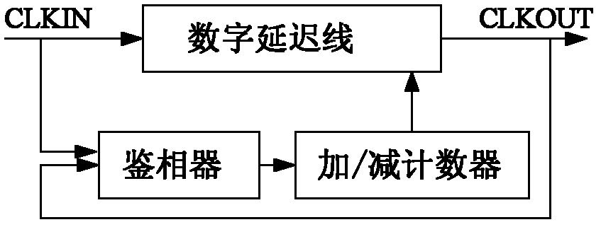
2) The counter controls the DLL; it replaces the register in the first category with a counter, thereby reducing the hardware of the controller, but its lock time and the number of required delay units are similar to the first category
3) Successive approximation DLL; successive approximation DLL can shorten the locking time through binary search algorithm, but its frequency range is relatively narrow
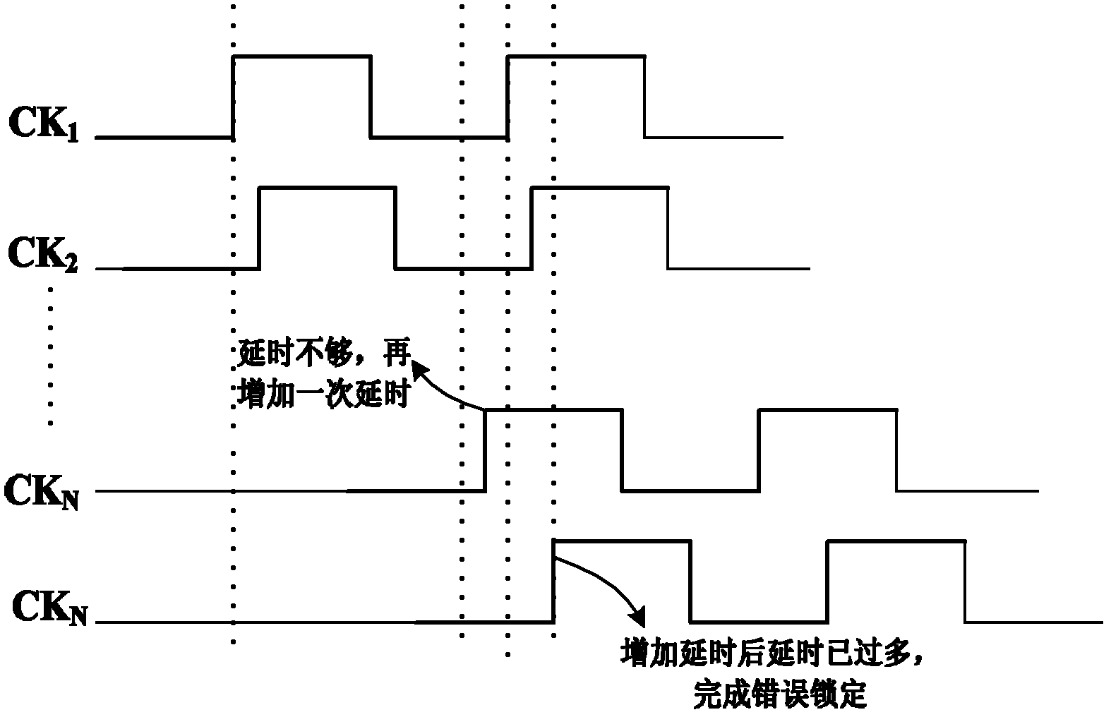
Since there is no detection mechanism in the locking process, only the input signal CLK is compared with the final delayed output signal CK N phasing situation, it is not possible to determine when the lock is complete when the CK N Whether the delay is in the range of meeting the locking conditions, so it is possible to form a wrong lock

Method used


Image

  • Counter control type delay-locked loop circuit with mistaken locking correction mechanism
  • Counter control type delay-locked loop circuit with mistaken locking correction mechanism
  • Counter control type delay-locked loop circuit with mistaken locking correction mechanism

Examples


Embodiment Construction

[0027] In order to make the technical features of the present invention more obvious and understandable, the present invention will be further described below in conjunction with the accompanying drawings and embodiments.

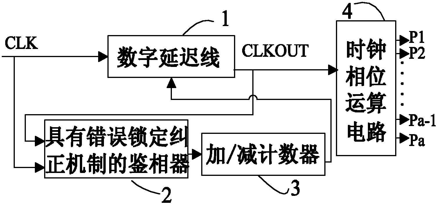
[0028] Such as image 3 As shown, the structure of the counter-controlled delay phase-locked loop circuit with error locking correction mechanism of the present invention includes 4 functional modules: digital delay line 1, phase detector 2, add / subtract counter 3, clock phase operation circuit 4. The digital delay line 1 is composed of (n+3) identical delay units, where n is any positive integer, and each delay unit is controlled by the output signal of the up / down counter 3, and the phase detector 2 compares the input clock and delay The phase of the output clock after the hour is controlled according to the comparison result of the add / subtract counter 3, and the clock phase operation circuit 4 selects the delay signal output by some delay units for pro...


PUM


Abstract

The invention relates to a counter control type delay-locked loop (DLL) circuit with a mistaken locking correction mechanism. The circuit comprises a digital delay line, a phase discriminator, an addition / subtraction counter and a clock phase arithmetic circuit. An input reference clock signal CLK is connected to the digital delay line and the phase discriminator respectively. The output of the digital delay line is connected to the phase discriminator and the clock phase arithmetic circuit. The output of the phase discriminator is connected to the input of the addition / subtraction counter. The output of the addition / subtraction counter is connected to the digital delay line. Whether the delay of a delayed output clock signal is consistent with a locking condition or not is judged through a locking process detection window, and the delay is timely regulated according to a detection result, so that mistaken locking is avoided, and a delay locking function is accurately realized. The circuit has the advantages that: the problem that the conventional DLL structure is easily mistakenly locked is effectively solved; moreover, the circuit has a wide frequency range and much phase output; and the yield of a chip can be improved.

Description

technical field [0001] The invention relates to a digital delay-locked loop circuit, in particular to a counter-controlled delay-locked loop circuit with an error locking correction mechanism. Background technique [0002] Phase-locked loop (PLL) and delay-locked loop (DLL) are widely used in large-scale integrated circuits to solve the problem of clock skew and adjust the delay of the clock signal. Compared with PLL, DLL has more advantages. It is a first-order system with good stability, shorter lock time, simple design, no jitter accumulation, etc., so DLL has gradually become the clock signal for delay adjustment. mainstream circuit. [0003] DLLs can be categorized as Analog DLLs, Digital DLLs, and Mixed-Mode DLLs. Analog DLLs and mixed-mode DLLs are more resistant to clock jitter and clock skew, but this also limits the frequency range. In addition, the analog DLL requires a longer lock time and a larger chip area, and the sensitivity of the analog circuit also make...

Claims


Application Information

Patent Timeline
Patent Type & Authority Applications(China)
IPC IPC(8): H03L7/08
Inventor 周洁陈珍海季惠才黄嵩人于宗光薛颜
Owner 58TH RES INST OF CETC
Learn More