Single line transmission device of cascade signals of LED (Light Emitting Diode) controlling and driving chip

A technology of LED chip and transmission device, which is applied in the field of LED control drive chip cascaded signal single-line transmission device, which can solve the problems of inconsistent transmission delay, high capital and manpower, and incorrect transmission of data signals, etc., to reduce the use of cables Quantity, high product qualification rate, stable and clear timing effect

Active Publication Date: 2012-07-18
UNIV OF ELECTRONICS SCI & TECH OF CHINA
View PDF6 Cites 35 Cited by
  • Summary
  • Abstract
  • Description
  • Claims
  • Application Information

AI Technical Summary

Problems solved by technology

For example, multiple LED drive circuits realize the transmission of data and instructions through data lines, chip select signals, clock signal lines, and latch signal lines. This communication method requires strict timing coordination between the signals on the four transmission lines. Once the timing is inaccurate, the data signal cannot be transmitted correctly, and the serial connection signal of the entire LED display system cannot be transmitted correctly, resulting in the paralysis of the entire LED display system
However, in actual production, due to the impedance mismatch on the transmission line, the inconsistency of the transmission delay, the insufficient drive capability of the driver, and the existence of external electromagnetic interference, the digital signal will experience various signal deformations and chaotic timing relationships during the transmission process. causing the transfer to fail
In order to solve these problems, the production and design side of the LED display system needs to invest a lot of money and a lot of manpower to ensure that the products are qualified.

Method used


Image

  • Single line transmission device of cascade signals of LED (Light Emitting Diode) controlling and driving chip
  • Single line transmission device of cascade signals of LED (Light Emitting Diode) controlling and driving chip
  • Single line transmission device of cascade signals of LED (Light Emitting Diode) controlling and driving chip

Examples


Embodiment Construction

[0020] Further description will be given below in conjunction with a specific example of cascading LED chips using the present invention, supplemented by related drawings.

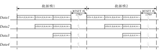
[0021] A. The cascade signal of the LED chip is transmitted in frame format, and the data frame received by each level of chip contains the following content: the rising edge is used as the synchronization signal indicating the arrival of data; Grayscale data; the length is the RESET signal represented by the low level of Treset.

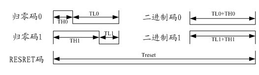
[0022] The data signal mentioned in the above content A is expressed in the form of a return-to-zero code, which is a code that represents 0 and 1 with two digital level signals with different duty cycles, and the code is transmitted when "0" or "1 ", the initial state (zero) will be returned within one symbol, and its relationship with the binary code is as follows figure 1 shown. The RESET signal is at a low level with a duration of Treset. Among them, TH0 is the high-level...


PUM


Abstract

The invention discloses a single line transmission device of cascade signals of LED (Light Emitting Diode) controlling and driving chip. The single line transmission device realizes the single line transmission of the cascade signal between various LED controlling and driving chips, which comprises the following steps: serial data signals transmitted to the chips are encoded; according to the received serial signals, a synchronous sampling clock is generated, and the data are collected; RESET signals in the serial signals are detected by the chips, and the collected data are sent out for display; and after the various levels of chips receive the data with fixed bit number, the subsequent data are reshaped automatically and transferred to the next level. According to the design, the receiving and the decoding of the data are completed by one signal line, when the linear transmission is conducted, the signals can be cascaded infinitely, so that the transmission of the cascade signals is simplified, and the signal line transmission device has the characteristics of quick speed and long transmission distance.

Description

technical field [0001] The invention relates to a coding method for serial transmission of digital signals between semiconductor devices, in particular to a single-line transmission device for cascaded signals of LED control and drive chips. Background technique [0002] In recent years, with the continuous deepening of research on semiconductor light-emitting materials, the continuous improvement of LED manufacturing technology and the development and application of new materials, breakthroughs have been made in ultra-high brightness LEDs of various colors, and their luminous efficiency has increased by nearly 1000 times, in terms of chromaticity, all colors in the visible light band have been realized, and are widely used in indicator lights, signal lights, display screens, landscape lighting and other display fields. [0003] At present, in most large-scale LED display systems at home and abroad, the main body of the communication system composed of LED control circuit an...

Claims


Application Information

Patent Timeline
Patent Type & Authority Applications(China)
IPC IPC(8): H05B37/02H04L1/00
Inventor 吕坚周云王璐霞江桥
Owner UNIV OF ELECTRONICS SCI & TECH OF CHINA
Why Eureka
Try Eureka