Burner, in particular for gas turbines

A burner, fuel distributor technology, applied in the direction of combustion chamber, combustion method, combustion equipment, etc.

Inactive Publication Date: 2012-07-18
SIEMENS AG
View PDF7 Cites 6 Cited by
  • Summary
  • Abstract
  • Description
  • Claims
  • Application Information

AI Technical Summary

Problems solved by technology

The difficulty now lies in the fact that the spoiler vanes with additional combustible gas passages meet the necessary strength specifications and at the same time have a long service life

Method used


Image

  • Burner, in particular for gas turbines
  • Burner, in particular for gas turbines
  • Burner, in particular for gas turbines

Examples


Embodiment Construction

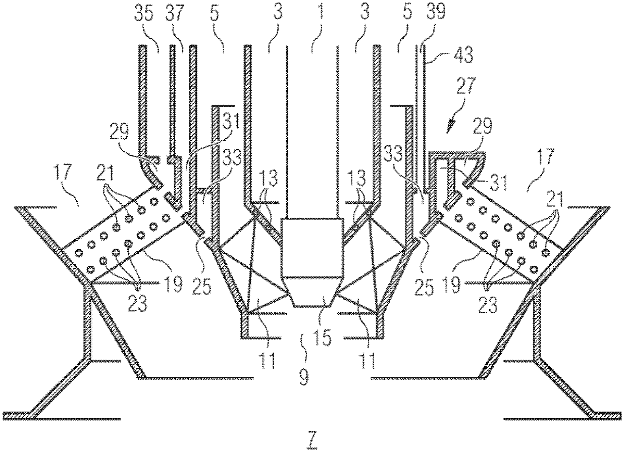
[0024] See below for a very schematic schematic diagram of the burner figure 1 , illustrating the basic design of the burner.

[0025] The burner, which may be used in a combustion chamber of a gas turbine if necessary in combination with a plurality of identical burners, comprises an internal control burner system and a main burner system concentrically surrounding the control burner system. Not only the control burner system, but also the main burner system, can optionally be operated with gaseous and / or liquid fuels, such as natural gas or oil.

[0026] The control burner system comprises an inner oil supply channel 1 which is concentrically surrounded by an annular inner combustible gas supply channel 3 . The inner combustible gas supply channel 3 is in turn concentrically surrounded by an inner air supply channel or inert substance supply channel 5 . In addition, a suitable ignition system (not shown in the figure) can be arranged in or on this air supply channel. The ...


PUM


Abstract

The invention relates to a burner comprising a central fuel supply arrangement (27), an annular air channel (18) surrounding said central fuel supply arrangement (27), for supplying combustion air and swirl blades which are arranged in the annular air channel (17), comprising first fuel nozzles (21) for introducing an essentially gaseous fuel into the combustion air, and second fuel nozzles (23) for introducing an essentially gaseous fuel into the combustion air. The first fuel nozzles (21) are supplied by a fuel distributor supply in the fuel supply arrangement (27), and the second fuel nozzles (23) are supplied by a fuel distributor channel (31) in the fuel supply arrangement (27). The fuel distributor supply comprises a supply pipe (55) which is connected downstream of the swirl blade (19), and an annular attachment (60). The supply pipe (55) is connected downstream of the annular attachment (60) and said annular attachment (60) is mounted upstream of the fuel distributor channel (31) when seen in the direction of flow. The invention also relates to a gas turbine comprising said type of burner.

Description

technical field [0001] The invention relates to a combustor and in particular a gas turbine combustor comprising a central fuel supply. Furthermore, the invention relates to a gas turbine. Background technique [0002] In view of the worldwide efforts to reduce the harmful emissions of combustion plants, especially in gas turbines, some burners with particularly low emissions of nitrogen oxides (NOx) have been developed in recent years. It is very valuable in this respect that these burners can be operated not only with one fuel, but also, where possible, with different fuels, e.g. oil and natural gas or a combination thereof, for increased supply security and Work flexibility. Such burners are described, for example, in EP0276696B1. [0003] The burner described in EP0276696B1 is a hybrid burner as used especially in gas turbine installations for premixed operation with combustible gas and / or oil. This burner consists of a central fuel supply in which is also integrated...

Claims


Application Information

Patent Timeline
Patent Type & Authority Applications(China)
IPC IPC(8): F23R3/14F23R3/28F23R3/36
CPCF23R3/286F23R3/36F23R3/14
Inventor A.贝彻M.卡诺沃尔夫A.克鲁格T.克里格S.斯塔林U.沃尔兹
Owner SIEMENS AG
Why Eureka
Try Eureka