
Upright bottle cleaning machine

A bottle washing machine, vertical technology, applied in the direction of cleaning hollow objects, cleaning methods and utensils, chemical instruments and methods, etc., can solve the problem of incompact structure, inability to insert bottle washing needle holders, and difficult to avoid containing no lubricating grease components and other problems to achieve the effect of convenient maintenance

Inactive Publication Date: 2012-07-25
上海千山远东制药机械有限公司
View PDF7 Cites 7 Cited by
  • Summary
  • Abstract
  • Description
  • Claims
  • Application Information

AI Technical Summary

Problems solved by technology

[0002] In the vertical bottle washing machines currently on the market, the lifting and swinging of the bottle washing needle frame is a movement formed by the combination of a set of lifting cams and a set of swinging cams; there are many ways to complete the rotation of the clamp turntable, mainly eccentric small The gear drives the large gear and the motor reducer directly drives the center to rotate. The transmission mode of this bottle washing machine is not compact. When the bottle washing machine runs at high speed, it cannot achieve accurate transmission, resulting in the inability of the bottle washing needle holder to be inserted into the ampoule or vial. Rinse it thoroughly
[0003] According to the requirements of the new GMP, the bottle washing machine should ensure that the rinse water and air do not contain grease. The current transmission components, whether it is the cam set or the gear movement, need grease lubrication, so it is difficult to avoid the rinse water and air of the bottle washing machine. Does not contain lubricating oil ingredients

Method used


Image

  • Upright bottle cleaning machine
  • Upright bottle cleaning machine

Examples


Embodiment Construction

[0015] In order to make the technical means, creative features, goals and effects achieved by the present invention easy to understand, the present invention will be further described below in conjunction with specific embodiments.

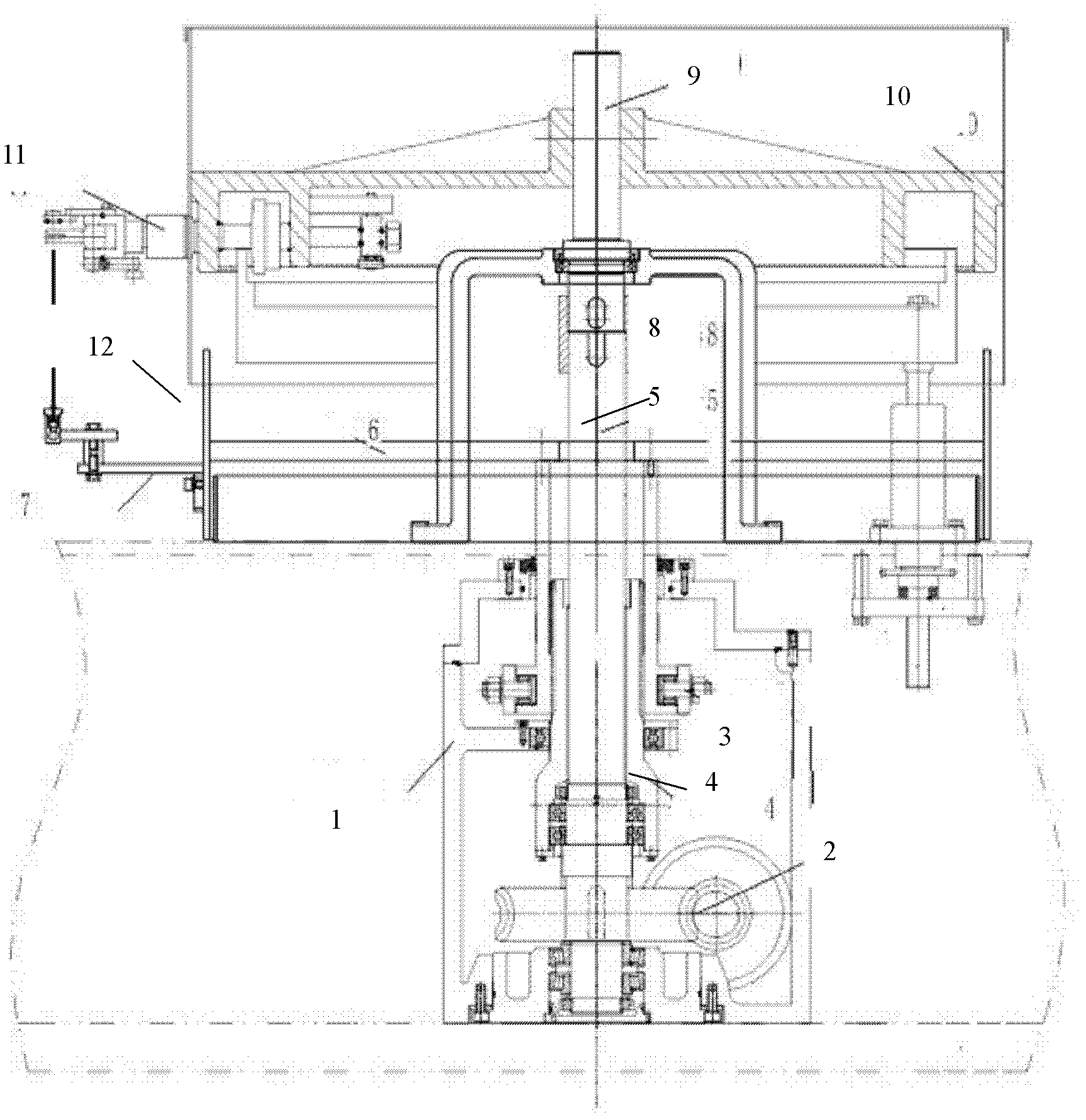
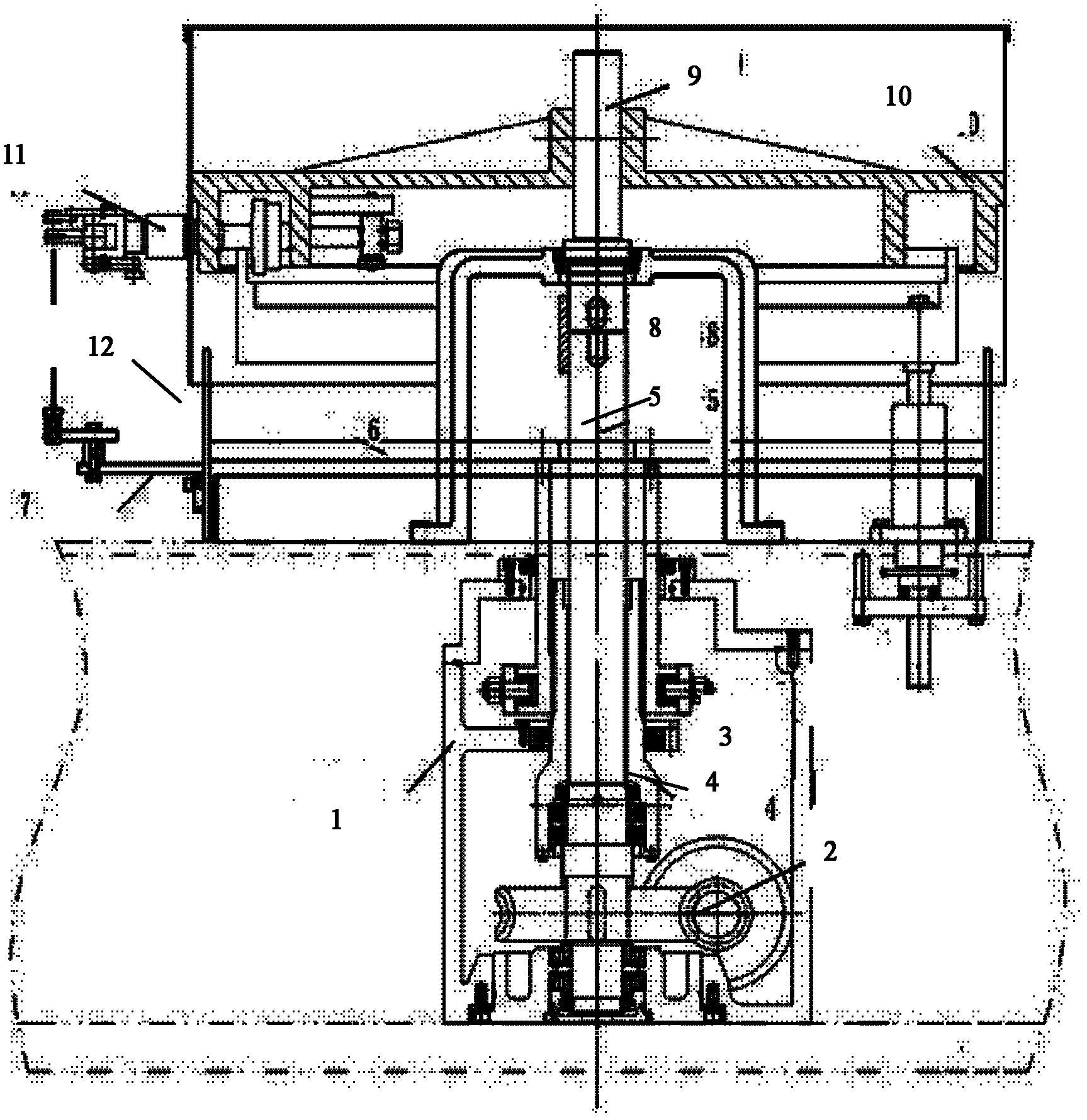
[0016] As shown in the accompanying drawings, a vertical bottle washing machine includes a station box 1, a worm gear transmission group 2, a lifting and swinging compound cam transmission group 3, a swinging hollow shaft 4, a central rotating shaft 5, a swinging cross 6, and a swinging needle. Frame 7, coupling 8, extended central shaft 9, central turntable 10, clamp 11 and swing ring 12.

[0017] A vertical bottle washing machine, comprising a station box 1, the station box 1 includes a turbine and worm transmission group 2, a lifting and swinging compound cam transmission group 3, a swinging hollow shaft 4 and a central rotating shaft 5, the turbine The turbine of the worm transmission group 2 is connected to the central shaft 5, the lifting an...


PUM


Abstract

The invention discloses an upright bottle cleaning machine, which comprises a work station box including a worm gear transmission assembly, a lifting swinging combined cam transmission assembly, a swinging hollow shaft and a central rotation shaft. The worm gear of the worm gear transmission assembly is connected to the central rotation shaft, the lifting swinging combined cam transmission assembly is connected to the swinging hollow shaft, the central rotation shaft is fixedly connected to an extension central shaft via a coupling, the extension central shaft is connected with a central rotary disc, the central rotary disc is provided with at least one group of pincers, the swinging hollow shaft is connected with a swinging cross which is connected with a swinging needle holder through a swinging ring, the swinging hollow shaft is fitted outside the central rotation shaft, lifting and swinging of the swinging needle holder are realized by one set of the lifting swinging combined cam transmission assembly in the work station box, rotation of the pincers rotary disc is realized by one set of the worm gear transmission assembly in the work station box, and the work station box is soaked below lubricating oil and sealed both at the end face and in the axial direction to ensure that main transmission causes no contamination to cleaning water and gas of the bottle cleaning machine.

Description

technical field [0001] The invention relates to the field of pharmaceutical machinery, in particular to a vertical bottle washing machine. Background technique [0002] In the vertical bottle washing machines currently on the market, the lifting and swinging of the bottle washing needle frame is a movement formed by the combination of a set of lifting cams and a set of swinging cams; there are many ways to complete the rotation of the clamp turntable, mainly eccentric small The gear drives the large gear and the motor reducer directly drives the center to rotate. The transmission mode of this bottle washing machine is not compact. When the bottle washing machine runs at high speed, it cannot achieve accurate transmission, resulting in the inability of the bottle washing needle holder to be inserted into the ampoule or vial. Rinse it thoroughly. [0003] According to the requirements of the new GMP, the bottle washing machine should ensure that the rinse water and air do not...

Claims


Application Information

Patent Timeline
Patent Type & Authority Applications(China)
IPC IPC(8): B08B9/28
Inventor 高云维黄永乐华昌彪
Owner 上海千山远东制药机械有限公司
Learn More